


11
MG.10.P2.22 - VLT is a registered Danfoss trademark
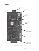
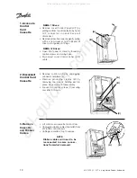
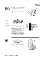
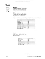
• On back of cassette, insert edge of
Modbus RTU option card into slot at side
of cassette (A).
• Secure opposite side of card with 2
self-tapping screws and washers provided
(B). Using a Torx T-10 screw driver, tighten
to 8 in-lbs.
4. Secure
Modbus RTU
Option Card
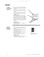
5. Wire
Modbus RTU
Option Card
Connector to
VLT 6000
Terminals
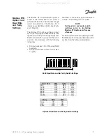
• Wire Modbus interface connector (24 V
power) pin 1 to VLT 6000 terminal 12 or
13.
• Wire Modbus interface connector (RTxD)
pin 2 to VLT 6000 terminal 69.
• Wire Modbus interface connector (com)
pin 3 to VLT 6000 terminals 39 and 61.
• Wire Modbus interface connector
(RTxD') pin 4 to VLT 6000 terminal 68.
• Plug Modbus interface connector into
bottom of Modbus RTU option card.
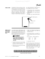
• Connect control card cassette to hinge
at top of drive.
• Connect ribbon cables.
6. Install
Ribbon
Cables
NOTE
Ribbon cables must be recon-
nected to same connections
from which removed.
NOTE
Use 18 to 22 gauge wire. Torque
terminals to 4.5 in-lbs. Modbus
interface connector terminals 5
and 6 are spares.
(B)
(A)
(spare)
(spare)
RTxD
RTxD'
Com
24V in
Pin 1
to terminal 12 or 13
to terminal 69 (-)
to terminals 39 and 61
to terminal 68 (+)
All manuals and user guides at all-guides.com


