


Technical Information
Output Configurations for PLUS+1® Controllers
520L0922
• Rev EA • Sep 2013
11
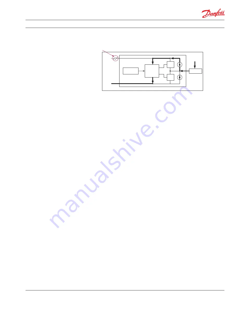
Below is a simple schematic to show how this can happen. The arrows indicate the path of current.
Open Wire to
Controller (continued)
2307
Load
Ground
+Batt
Logic circuits
FET
Configuration
FET
+Batt
Open
The only way to remove the current completely is to source the load current from the controller,
through another output. If you are driving an EDC type load (dual coil) and are driving both coils to
get a forward / reverse type function, this could be done by driving one coil bi-directionally with no
additional outputs consumed.
If there are enough valves connected to the controller to provide multiple current paths, you might
be able to reduce the amount of current in each valve enough so that it is no longer above the
threshold of any one valve.
If you have multiple power connections to the controller, you might be able to reduce the occurrence
of the fault enough so that it no longer a significant risk (rates below 100 on the System FMEA). You
may also be able to improve the wiring integrity to minimize the occurrence of the fault.
Open Ground Wire to Load
Open Load Ground Wire
If you are using a dual coil device with a common ground for bidirectional control, this could be a
problem if the common ground wire is open. When using this configuration, the current can flow out
of the sourcing output and will try to find a path to ground. If you have the other coil connected to a
low impedance source, the current can flow through both coils. This may cause unintended or
erroneous movement of the controlled device. Connecting the non-active coil to a high impedance
source will prevent this from occurring. See the recommended configurations
Open Wire to
Controller
, page 10 and above, for driving this type of load.