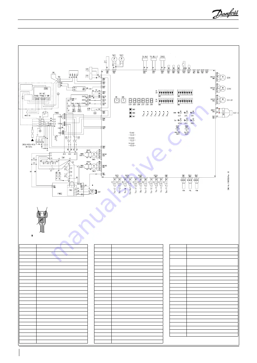
background image

4. Installation

Wiring Diagram

Symbol

Name

C1,2

Electrolytic capacitor

C3

Filter capacitor

CH1

Crankcase heater

CM1

Compressor motor

CNA-Z

Connector

CT1

Compressor current

DM1

Diode module

EEVG

EEV for middle pressure receiver inlet

EEV-LB1

JEEV for liquid bypass

EEVSC

EEV for subcooling coil

F

Fuse

FMC1,2

Inverter cooling fan

FMO1,2

Fan motor

IPM1

intelligent power module

J10

Spare

J11,12

Power supply, voltage switching

J13

External input signal type switching

J14~16

Spare

L1-1,2

DC reactor

L3

Reactor

LED1

Main, inspection (red)

LED2

Main, normal (green)

LED3

Main, service (green)

LED4~6

7-segment LED (function display)

LED7~9

7-segment LED (data display)

LED10

Sub, normal (green)

LED 11

Sub, inspection (red)

Symbol

Name

LED 12

Sub, service (green)

OLS1-2

Oil level sensor

PSH

High pressure sensor

PSL

Low pressure sensor

PSM

Middle pressure sensor

PWB1~3,5~7

Printed wiring board

R1-1,2,3

Inrush suppression resistance

R3-1,2

Discharge resistance

R5

Drop resistance

R6

Termination resistance

R7

Filter resistance

SVHG1

Solenoid valve for hot gas bypass

SV-INJ1

Solenoid valve for gas injection

SV-OIL1-2

Solenoid valve for oil return

SW1

Compressor low pressure control setting (10s)

SW2

Compressor low pressure control setting (1s)

SW3-1~3

Spare

SW3-4

Protection start II cancel

SW3-5

Gas cooler fan control

SW3-6

Spare

SW3-7

Compressor total operation time reset

SW3-8

Spare

SW4-1~4

Model selection

SW4-5~8

Spare

SW5-1~3

For target middle pressure adjustment

SW5-4,5

Spare

SW5-6~8

Pressure check operation mode

Symbol

Name

SW6-1~3

Spare

SW6-4

Presence of subcooling suppression control

SW6-5

Oil level error/oPE display switching

SW6-6

Presence of regular inspection and 
maintenance contract

SW6-7

Oil level error

Sw6-8

Spare

SW7

Data erase/write

SW8

7-segment display (1s)

SW9

7-seqment display (10s)

TB1,2

Terminal block

Tho-A

Outdoor air temp. sensor

Tho-C1

Under dome temp. sensor

Tho-D1

Discharge pipe temp. sensor

Tho-G1

Gas cooler temp. sensor 1 (inlet)

Tho-G2

Gas cooler temp. sensor 2 (outlet)

Tho-INJ1

Gas injection inlet temp. sensor 1

Tho-M

Middle pressure receiver inlet temp. sensor

Tho-P1

Power transistor temp. sensor

Tho-R

Liquid feed pipe temp. sensor

Tho-SC

Subcooling coil temp. sensor

Tho-S

Suction pipe temp. sensor

ON-OFF SW

Operation switch

52X1-1,2

Magnetic contactor for CM

63H1-1

High pressure switch

Notes


1. This drawing shows the electrical circuit of CO2 condensing unit. 
2.  Dotted line (----- ) shows the wiring on site. 

Long dashed double-short dashed line (----- ) shows installation on site.

3. Separate signal line from power line. 
4.  CNG1,CNG2,CNS1,CNS2 and CNS3 are no voltage contact inputs. 

If they will be used, use the attached harness for level input.

5.  Output of CNH,CNY,CNZ1 and CNZ2 is 12V. Maximum current is less than 20mA (+ side (1 PIN side) is common) . 

If they will be used, use the attached harness and be sure to connect to unit relay (Coil resistance of 7502 or more 
provided on site).

U (red)

W (Blue)

Enlarged drawing of 

compress terminals

V (White)

Ex

ter

nal output 2

Ex

ter

nal output 1

Er

ror output

Oper

ation output

Oper

ation in

tput

G

as c

ooler fan sno

con

tr

ol input

Multistage  demand input

C

ompulsor

y oil 

retun c

on

tr

ol input

ON - OFF SW

ASSLY CO2 MODULE CONTROLLER

Super Link 

Adapter PCB 

PWB6

User interface

MMILDS

12VDC 

Power

Module controller

Circuit breaker 

for cabling

Earth leakage 

breaker

Power source

Inverter PCB

Compressor terminal 

See enlarged view

Control PCB

PWB1

Noise filter PCB

Power PCB PWB5

Remote PCB PWB7

Ready connector

30

AB408540130380en-000102

© Danfoss | Climate Solutions | 2023.02

Application Guidelines

Summary of Contents for Optyma OP-UPAC015COP04E

Page 1: ...Optyma iCO2 condensing units R744 50 Hz Application guidelines www danfoss com...

Page 2: ......

Page 3: ...allation work 23 4 3 Delivery and installation of the condensing unit 23 4 4 Caution for piping work 24 4 5 Caution for electric wiring work 27 5 System design recommendations 31 5 1 Airtight Method 3...

Page 4: ...ly to specified torque If they are not tightened securely it could cause fire or electric shock owing to overheat on the terminal Usespecifiedcablesforwiring andconnectthemsecurely avoidingexternalfor...

Page 5: ...cation or disposal remove the refrigerant pipe after stopping the compressor If it is operated while the refrigerant pipe is removed and the gate valve is opened it could inhale air or other and raise...

Page 6: ...pean Market Children should be supervised to ensure that they do not play with the appliance In the Australian and New Zealand market Restriction on use of equipment This appliance can be used by chil...

Page 7: ...ething on the condensing unit It could cause injury if you fall damage the machine or drop the object Refrain from touching hands on the gas cooler fin directly You could get hurt CAUTION When washing...

Page 8: ...pressure side of scroll rotary compressor Care must be taken particularly when charging or discharging oil during maintenance service or test run Optyma iCO2 combines our market leading expertise in...

Page 9: ...ance 62 0 dB A Enclosure painting specification Stucco white PED catagory II Approval CE UKCA Compressor Type Hermetic inverter Type Oil Diamond freeze MA68 Displacement 15 CC Technology Scroll Rotary...

Page 10: ...Oil pod Accumulator Subcooling coil temperature sensor Middle pressure receiver inlet temperature sensor EEV for middle pressure receiver inlet Gas cooler temperature sensor inlet Gas cooler temperat...

Page 11: ...s with a wall If the unit installed in succession 10mm spaces is enough 1 All dimensions are in mm 2 Dimensions are not to scale Wall height H4 Wall height H3 Service space Service space Wall height H...

Page 12: ...ology 2 stage Scroll Rotary Control box pre wired E panel Yes Fin and Tube condenser Yes Fan speed controller Yes Main switch circuit breaker Yes Filter drier Yes Sight glass Yes Crankcase heater Yes...

Page 13: ...frigerant E Housing Service Pressure Maximum working pressure F Supply voltage Rated Load Ampere Maximum Continuous Current G Serial Number and bar code Danfoss IP24 PSHP PSLP MP PTHP PTLP MP PED Cate...

Page 14: ...35 outlet 6 35 17 SENSOR LP SSA551D031 0 093 105 85 55 Carton box Middle pressure sensor PSM HSK BC 016 Range 0 to 100bar Connection size 6 0 18 VALVE CHECK SSA385A053 0 185 150 125 25 Vinyl bag Chec...

Page 15: ...725 160 160 80 Carton box Fan motor UP12D23 GTEW Rated output 16W Rated voltage 230V 1 phase 50 60Hz 53 SENSOR ASSY LCA551A002 0 052 300 175 10 Vinyl bag THO G1 G2 54 SENSOR ASSY LCA551A002A 0 058 30...

Page 16: ...tapes When using the wiring refer to the External input harness installation manual page 48 Dryer 1 Install in liquid pipe Dryer pipe diameter need to reduce with reducer to connect liquid pipe This...

Page 17: ...rature exceeds 5 C rated capacity decreases due to the operation of the protection control and rated capacity decreases as the evaporation temperature increases Notes 1 When evaporating temperature ex...

Page 18: ...SOUND POWER dB A 1 1 OCTAVE FREQUENCY HZ Acoustic Sound Spectrum 50Hz Weighted dB A Condensing unit Model OP UPAC015COP04E Condensing Unit Code 114X6003 Housing Compressor CO2 Electrical code Compres...

Page 19: ...x 764 x 1691 5 340 590 340 510 850 375 345 381 726 697 Model Item Compressor speed min 1 Fan speed min 1 OP UPAC015COP04E 6240 1000 1 Note Dimensions L1 X1 X2 and L2 Y1 Y2 indicate the position of ins...

Page 20: ...in a range of 5 deg to 40 deg Use this condensing unit within the following operation ranges Item Unit Specifications Refrigerant R744 Evaporation temperature C 45 5 Low pressure LP bar abs 8 3 30 5 S...

Page 21: ...ith which the refrigerant flow speed in the heat exchanger piping is within the oil returnable range in the following figure Range of gas flow speed at the evaporator outlet during rated operation Ins...

Page 22: ...rigerant oil 3 Oil return operation Delivery Hand over and instruction Plan the project Vacuum drying R744 R744 High pressure side Max 140 Bar Medium low pressure side Max 80 Bar indicates the airtigh...

Page 23: ...levelness of foundation can prevent vibration and noise The foundation must be larger than the shadowed areas in the above figures larger than the front of the fixing legs of condensing unit The foun...

Page 24: ...well designed and practiced the refrigerant piping work plays a critical influence over the capacity life or failures on the refrigerating unit Design and practice the piping work as instructed below...

Page 25: ...from the factory Make sure to keep the seal intact till just before connecting pipes in order to keep out dirt or moisture Release to the atmosphere must be made through service ports at the high med...

Page 26: ...at site 1 Pipe diameter Prepare refrigerant pipes at site Pipe joints are as shown below 2 Suction pipe Normally adjust the pipe size to the end diameter of copper pipe at the joint of condensing unit...

Page 27: ...not connect the ground wire to a gas pipe lighting rod or telephone grounding wire If improperly grounded an electric shock or malfunction may result Never connect the grounding wire to a gas pipe bec...

Page 28: ...e drop at 2 V Electric characteristics for 50Hz Item Unit OP UPAC015COP04E Nominal output kW 6 4 Power supply 3P 380 400 415 V 50 Hz Electric characteristics Power consumption kW 10 54 10 54 10 54 Ope...

Page 29: ...pillary 20 Sight glass 21 Under dome temperature sensor 22 Injection inlet temperature sensor 23 Discharge pipe temperature sensor 24 Subcooling coil temperature sensor 25 Middle pressure receiver inl...

Page 30: ...ion and maintenance contract SW6 7 Oil level error Sw6 8 Spare SW7 Data erase write SW8 7 segment display 1s SW9 7 seqment display 10s TB1 2 Terminal block Tho A Outdoor air temp sensor Tho C1 Under d...

Page 31: ...n the manifold If the pressure drops it leaks at some places Find and repair the leak spots When it leaks check welded section and screwed section using foaming liquid Absolute pressure at measurement...

Page 32: ...to restore before restarting the equipment If it is operated with the coil removed it could break down the unit Middle pressure side service port Oil service port Low pressure side service port High p...

Page 33: ...akly acidic it is necessary to dry sufficiently by the vacuum drying Fig 20 Start evacuation from the low pressure side to prevent the reverse phase on the compressor Vacuum sufficiently for 2 to 3 ho...

Page 34: ...er The vacuum pump is connected to the service port at the low pressure side only at that time In the event that the pipe is long or there is an oil sump in the evaporator the condensing unit oil reta...

Page 35: ...ntity unit length of Lb1 pipe x Lb1 m Oil quantity unit length of Lb2 pipe x Lb2 m Oil quantity unit length of Lb3 pipe x Lb3 m Oil quantity unit length of Lb4 pipe x Lb4 m Oil quantity unit length of...

Page 36: ...ent pipe length Piping refrigerating oil quantity cc 16 cc m 5 System design recommendations 3 Additional condensing unit oil quantity Additional condensing unit oil is calculated to be 1 140 cc from...

Page 37: ...temperatures change widely 4 The oil become colorless and transparent 5 Since the unit inside becomes in the state of vacuum during the replenishment of condensing unit oil pay utmost attention not to...

Page 38: ...g unit oil with the manual pump When the pressure becomes higher than the balance pressure open the valve at the oil service port and charge the condensing unit oil 4 After charging oil close the valv...

Page 39: ...on temperature setting 5 C Evaporation temperature setting 5 C 10 2 12 2 2 Refrigerant quantity for connected show case or unit cooler Refrigerant quantity for connected show case or unit cooler Check...

Page 40: ...System design recommendations 5 6 4 Maximum refrigerant charge quantity Confirm that the refrigerant charge quantity as calculated in the step 5 6 3 is not larger than the maximum refrigerant charge q...

Page 41: ...gerant charge to stopped compressor Charge liquid refrigerant from the medium pressure service port of vessel unit When the unit is energized turn off the unit s power supply Turn the dip switch SW5 7...

Page 42: ...n short circuited CNS3 Brown Compulsory oil return control input Valid when short circuited Use connectors fixed with tapes on the outer wall of the control box CNG1 Blue Gas cooler fan snow control i...

Page 43: ...al board using M3 5 crimp terminal as shown in the sketch below Use an adequate screwdriver to tighten terminal screws If it is tightened too much it could destroy screws For the tightening torque of...

Page 44: ...tion shipping washers are not used on the compressor Since this product does not use anti vibration shipping washers it is not necessary to remove them before operation 6 Turn on the source power supp...

Page 45: ...the refrigerant system has been opened the system has to be flushed with dry air or nitrogen to remove moisture and a new filter dryer has to be installed If evacuation of refrigerant has to be done...

Page 46: ...nical or handling equipment according to weight It is recommended not to open the packaging before the unit is at the final place for installation Handle the unit with care The packaging allows for th...

Page 47: ...Compressor opened or returned unsealed Rust water or leak detection dye inside the compressor Use of a refrigerant or lubricant not approved by Danfoss Any deviation from recommended instructions pert...

Page 48: ...eaders in our business and positioned us as distinct variable speed technology specialists Today we operate from engineering and manufacturing facilities spanning across three continents AB40854013038...

Reviews: