


Instructions
8 | AN405821998738en-000102 - 118A5495A
© Danfoss | Climate Solutions | 2023.02 | LCA012A024
• The installation in which the condensing unit is installed must comply to Pressure Equipment Directive (PED) no. 2014/68/EU. The Optyma iCO2 condensing unit
assembly (partially completed assembly) certified for PED by Notified body (Vincotte - notification number 0026).
• It is recommended to install the unit on rubber grommets or vibration dampers (not supplied).
• Slowly release the nitrogen holding charge through the schrader port.
• Connect the unit to the system as soon as possible to avoid oil contamination from ambient moisture.
• Avoid material entering into the system while cutting tubes. Never drill holes where burrs cannot be removed.
• Braze with great care using state-of-the-art technique and vent piping with nitrogen gas flow.
• Connect the required safety and control devices. When the schrader port is used for this, remove the internal valve.
• It is recommended to insulate the suction pipe up to the compressor inlet with 19 mm thick insulation.
• Copper piping material should comply with EN12735-1. And all pipe joints should comply with EN14276-2
• At filed installation, support to added according to size and weight. Recommended maximum spacing for pipe support as per EN12735-1 & EN12735-2
Connecting pipes shall be made before opening the valves to permit refrigerant to flow between the refrigerating system parts.
Design and practice the piping work as instructed below.
• Sufficiently wash the inside of low pressure device, pipes, etc., to remove dirt or moisture,
and dry them before use. Use always a pipe cutter to cut refrigerant pipes, and blow off dirt
with nitrogen, or air, before connection. (Avoid to use a saw, or grinder, because it could
produce a lot of chips.)
• Use the nitrogen gas blow when brazing pipes to prevent oxide scale.
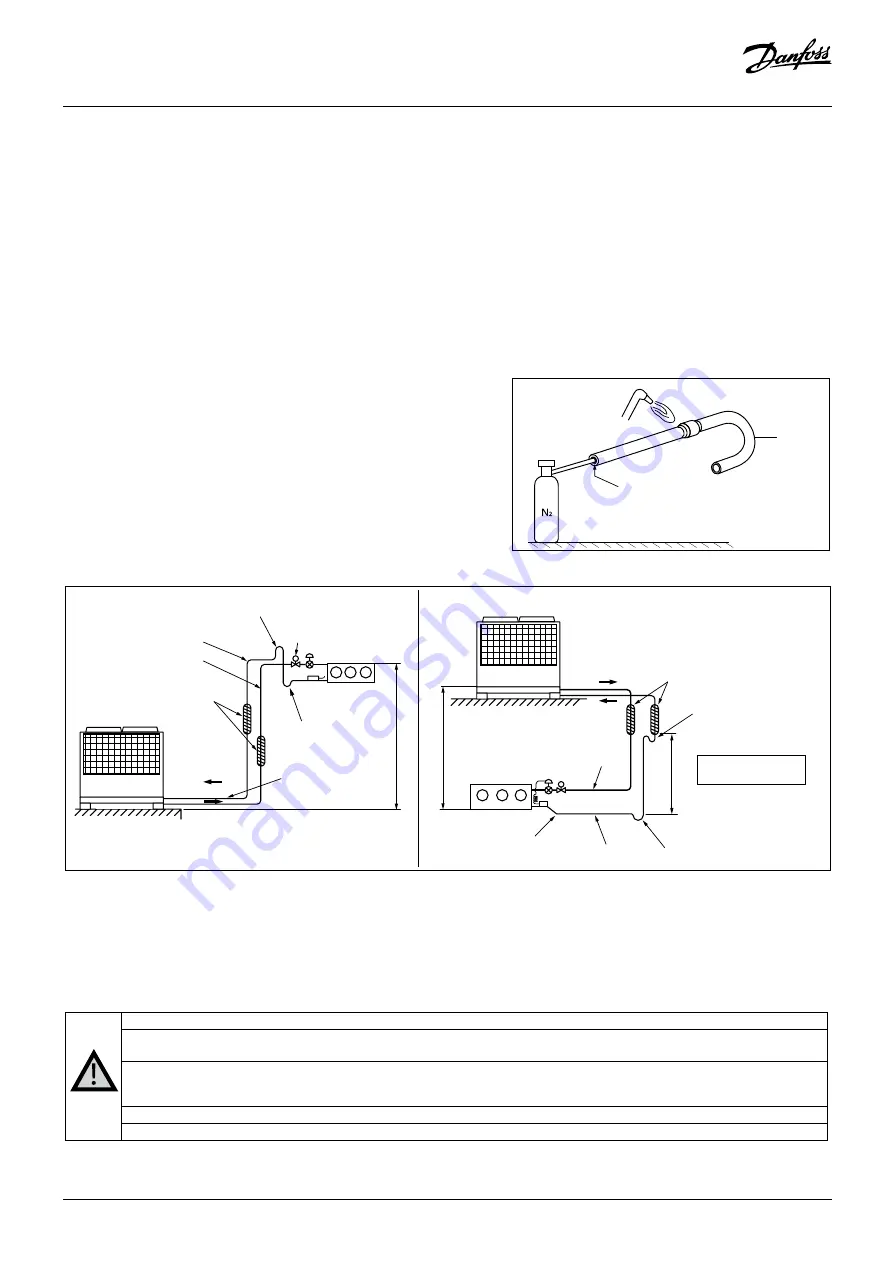
• Where the condensing units is positioned lower than the low pressure device, limit the level
difference between them no larger than 5 m or, if it is positioned higher, no larger than 22
m. Length of piping between them needs to be no longer than 100 m. (When the level
difference, or piping length, exceeds these standards, special measures may be required,
such as the enlargement of pipe diameter.)
Typical instillation
5 m or less
22 m or less
Evaporator
Suction pipe
Liquid pipe
Suction pipe
Liquid pipe
Position the liquid solenoid
valve closer to the expansion
valve more than the main unit.
Trap to prevent standing
liquid in the heat sensing
tube
Step to prevent standing
liquid in the heat sensing
tube
Secure a downward
slope of 1/200 to
1/250
Loop to prevent oil return
during operation stop
Heat insulate the liquid, suction
pipes over entire length.
Evaporator
5 m or less
Insulate the liquid, suction pipes
over entire length.
Oil U trap at every 5 m of pipe length
Oil return trap
Use Ø19.05 pipe for
vertical pipe going up
• The suction piping connected to the compressor must be flexible in 3 dimensions to dampen vibrations. Furthermore piping has to be done in such a way that oil
return for the compressor is ensured and the risk of liquid slug over in compressor is eliminated.
• Take care to avoid direct contact between suction and liquid pipes without insulation material too large temperature difference.
• The condensing unit is charged with Nitrogen gas at approx. 1.0 bar at shipping from the factory. Make sure to keep the seal intact till just before
connecting pipes in order to keep out dirt or moisture. Release to the atmosphere must be made through service ports at the high, medium and low sides.
*Dryer (accessory of refrigerant machine) is recommended to install in liquid pipe. Also strainer is recommended to install before the low pressure expansion valve.
Note on R744
Refrigeration cycle pressures (airtight test pressure, operation pressure, etc.) become approx. 4 times larger than the same of R404A.
Wall thickness of refrigerant pipes varies depending on the refrigerant and pipe size. Check if specified thickness is observed, and correct if necessary.
It could vary depending on pipe materials as well.
Ester oil is used as the condensing unit oil for the refrigeration cycle of R744.
In order to avoid contamination with impurities such as moisture, dirt, etc., as much as possible, the same fundamental control as synthetic refrigerant is required
at the installation of refrigerant piping.
Practice thorough control on the storage and curing of pipes to protect them from dirt or moisture.
Nitrogen blowing before brazing to prevent oxide scale.
Brazing
Pipe
Packing
Nitrogen gas cylinder
Nitrogen gas cylinder
Packing
Pipe
Brazing
Fig. 4
Fig. 5
Fig. 6