


Instructions
118A5495A - AN405821998738en-000102 | 11
© Danfoss | Climate Solutions | 2023.02 | LCA012A024
3. Liquid piping
• Install the liquid solenoid valve just before the expansion valve.
• If the liquid feed piping is overheated by the effect of other heat source, it generates flash gas, reducing
the cooling capacity. Run the liquid feed piping at a place as cool as possible. Where it passes at a place
at high temperature by any chance, insulate it.
General recommendation
Select pipes PS 80 bar. Ensure with your supplier that pipe material can support bending keeping PS
80 bar.
Downward slope
Eliminate trap.
Downward slope
Piping work at site
1. Pipe diameter
Prepare refrigerant pipes at site. Pipe joints are as shown below.
2. Suction pipe
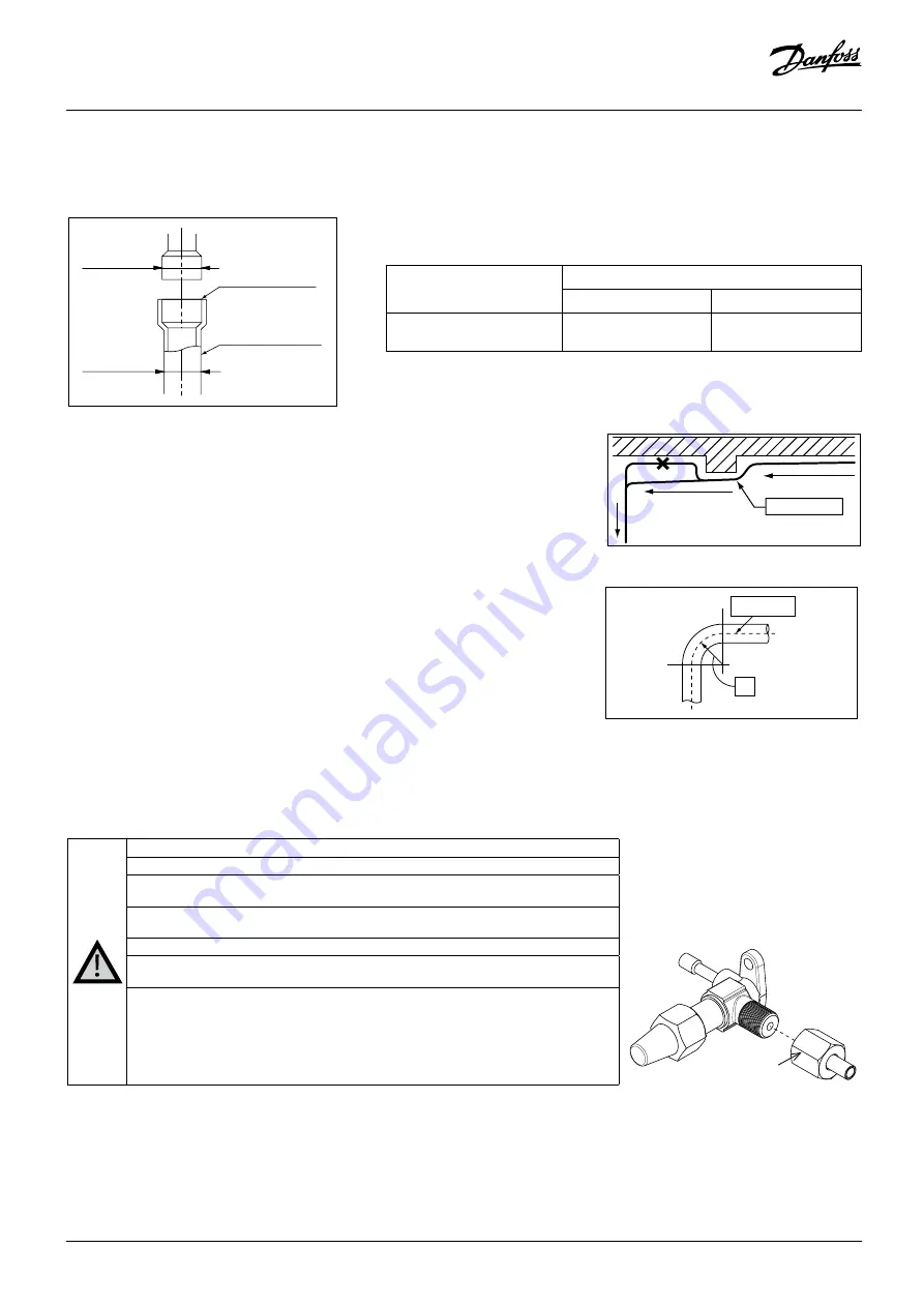
• Provide a downward slope (1/200 to 1/250) at the sidewise run of suction pipe. To return lubrication
oil smoothly, do not provide a trap at the sidewise run section. Where heights differ larger than 5 m
between the condensing unit and the low pressure device, provide a small trap.
Pipe dia.
Pipe dia.
Pipe prepared at site
Pipe connection
via socket
Type
Connecting pipe dia. (Example) (mm)
Suction pipe
Liquid pipe
OP-UPAC015COP04E
Ø19.05 (Brazing)
Ø12.7 (Brazing)
*Pipe wall thickness shows that of C1220T 1/2H.
Center line
R
Dimension
Start evacuation from the low pressure side to prevent the reverse phase on the compressor.
Vaccum 4 hours to 0.67 mbar.
Use a vacuum pump with a higher exhaust speed. (Conventional small pumps with exhaust
speed of 20 to 30 l/min, which are in use widely, will take too much time.)
Install a vacuum pump adaptor to prevent oil from returning from the pump to the refrigeration
cycle.
Use a manifold valve and a charge hose special to R744 (CO2).
A joint (Reducer) to install on the service valve is included in the accessories. When performing
the airtight test or vacuuming, finish the connection form of the joint according to purposes.
When the degree of vacuum rises, presence of moisture, or leaks, is suspected. Check for
moisture, or leaks. (Special vacuum dry)
i. Vacuum dry (1st).
ii. Vacuum dry (1st). : Pressurize nitrogen gas to 0.5 bar, and charge. Use nitrogen always.
iii. Vacuum dry (2nd).
iv. Ultimate vacuum must be maintained at -1 bar after letting it alone. If it is not, repeat the
vacuum dry and vacuum break.
Note for R744 (CO
2
)
Since R744 (CO2) may corrode metals if it solves into water, becoming weakly acidic, it is necessary to dry sufficiently by the vacuum drying.
Reducer
Fig. 10
Fig. 11
Fig. 12
Fig. 13