VI.B1.B4.6B
© Danfoss 05/2006
5
1.0 Handling
1.1 Storage
- Storage temperature -20° to +65°C
dry; free of dirt
- A desiccant or heating to prevent
condensation is necessary in damp
rooms.
- Don't damage the paintwork.
1.2 Transport
- Transport temperature -20° to
+ 65 °C.
- Protect against external force
(impact, vibration etc.).
- Don't damage the paintwork.
1.3 Handling before installation
- If flange covers are fitted, remove
shortly before maintenance !
- Protect against atmospheric
conditions e.g. wetness (applicate a
desiccant).
- Correct handling protects against
damage.
2.0 Description
2.1 Scope of applications
Line regulating valves with a
defined characteristic for heating
and cooling systems. The plant
designer is responsible for selecting
the correct valve for the purpose.
Note:
Do not use MSV-F2 valves for
handling steam!
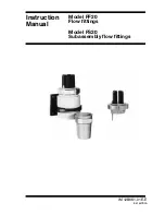
2.2 Operating principles
The valve is closed (cone/seating
function) by turning the hand wheel
clockwise.
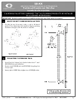
- Position of the plug at DN 50-150
is shown on two digit display. The
outer digit shows the basic setting
and the internal digit shows every
tenth of the turn. See Fig. 1.
- Position of the plug at DN200-300
is shown on the longitudinal
scale. See Fig. 2.
3.0 Installation
General notes on installation:
The following points should be taken
into account besides the general
principles governing installation work:
- Remove flange covers if present.
- There must be no foreign bodies
inside the valve or piping.
- Pay attention to the direction of flow:
see markings on the valve
- Valves can be installed with the
spindle pointing in any direction, but
the preferred spindle position is
vertical.
- Reference for isolation:
If media-temperatures < ambient
temperatures - ask manufacturer.
- Installation upside down only if the
medium is clean.
- Centre packings between the
flanges.
- Install measuring nipples before
valve is filled with water. See
accessories in the datasheet MSV-F2.
- Connection flanges must mate
exactly.
- All parts must be free from stress
after installation.
- The valve must not serve as a fixed
point. It must be carried by the
piping.
- Protect the valve from dirt, especially
during construction work.
- Install compensators to compensate
for thermal expansion of the piping.
- It is forbidden to heat the valve to
above its service temperature (see
data sheets), for instance by welding,
grinding, etc.
- To ensure that the valves function
correctly, the pipe run should be
straight for at least 5D upstream and
2D downstream of the valve.
4.0 Presetting and locking the
handwheel
4.1: DN 50-150:
a: Position of the plug at DN 50-150 is
shown on two digit display. The outer
digit (a) shows the basic setting and
the internal digit (b) shows every tenth
of the turn. See Fig. 4.
b: Remove cover plug (c) by introducing
a screwdriver in the slot and gently
prising it out. See Fig. 5.
c: Turn the hand-wheel clockwise and
close the valve fully. Digital display
shall show 0,0. Turn the hand-wheel
counter clockwise to required value of
presetting by using the setting table
(i.e. 4,5, see Fig. 4).
d: Turn the inner adjustment screw (d)
clockwise until it seats. Use enclosed
3mm allen key for DN 50 and 4 mm
allen key (e) for DN 65-150. The valve
now can be closed, but not opened
more than the setting value. See Fig. 5.
e: Optionally you can lock the hand-
wheel and protect the setting. Fit the
enclosed clip (f) in the cut-out in the
hand-wheel. Thread the sealing wire
(g) through the holes on the clip, hand-
wheel and lead seal. Fit the lead seal.
See Fig. 6.
4.2: DN 200-300
a: Turn the hand-wheel clockwise and
close the valve fully by hand
(“0” position).
b: Unscrew the cap (h). See Fig. 7.
c: Turn the hand-wheel counter clockwise
to required value of presetting by
using the setting table.
d: Turn the stroke limiter (i) clockwise
until it seats. Protect it by fixing the lock
nut (j).
e: Screw on the cap.
ENGLISH