pressure increases by an equal amount on the other gauge. Again note the angular position of the
wrench.
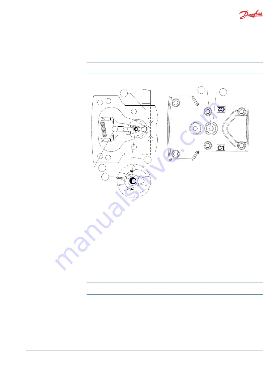
The illustration shows how the cam on the adjusting pin rotates to adjust for neutral position after
the pump is re-installed.
Neutral adjustment (EDC bottom view)
P109514
1
5
6
2
4
3
1. Control spool
2. Adjusting screw (cam)
3. Feedback pin
4. Maximum adjustment less than 120 deg.
5. Adjusting screw
6. Lock nut
5. Rotate the neutral adjusting screw clockwise half the distance between the wrench positions noted
above. The gauges should read the same pressure, indicating that the control is in its neutral position.
6. Hold the neutral adjusting screw stationary and tighten the lock nut. Torque to 10 Nm [7 lbf•ft]. Do
not over torque the nut.
7. When the neutral position is set, stop the prime mover, remove the gauges, and install the gauge
port plugs. Reconnect the external control input.
A small pressure differential of 1.5 bar [22 psi] or less is acceptable. Achieving zero differential is
usually not possible.
Mechanical/Hydraulic Neutral Adjustment
Servo Adjustment
1. Run prime mover at 1800 min
-1
(rpm).
2. If using a PWM signal, ensure the signal is off. Check the servo pressure gauges. Ensure the differential
between M4 and M5 is less than 1.5 bar [22 psi].
Service Manual
MP1
Adjustments
©
Danfoss | April 2019
AX00000244en-000201 | 49


