background image

23

INSTALLATION AND SERVICE

System cleanliness

System contamination is one of the 
main factors that aff ects  equipment 
reliability and compressor service life. 
Therefore it is important to take care 
of the system cleanliness when as-
sembling a refrigeration system. Dur-
ing the manufacturing process, circuit 
contamination can be caused by:

z

 Brazing and welding oxides,

z

 Filings and particles from removing 

burrs from pipe-work,

z

 Brazing fl ux,

z

 Moisture and air.

Only use clean and dehydrated, 
refrigeration-grade copper tubes and 
silver alloy brazing material. Clean all 
parts before brazing and always purge 
nitrogen or CO

2

 through the pipes 

during brazing to prevent oxidation. 

If fl ux is used, take every precaution 
to prevent the leakage of fl ux  into 
the piping.  The use of fl ux core or 
fl ux coated braze wire or rod instead 
of brush applied paste fl ux is strongly 
recommended. Do not drill holes 
(e.g. for schrader valves) in parts 
of the installation that are already 
completed, when fi lings and burrs 
cannot be removed. Carefully follow 
the instructions below regarding 
brazing, mounting, leak detection, 
pressure test and moisture removal. 
All installation and service work shall 
only be done by qualifi ed  personnel 
respecting all procedures and using 
tools (charging systems, tubes, vacuum 
pumps, etc.) dedicated for R404A and 
R507A.

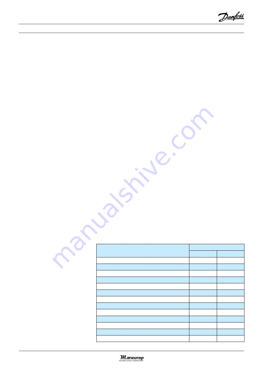
Compressor handling, 
mounting and connection

Component

Torque (Nm)

Min.

Max.

Rotolock suction valve, NTZ048 - NTZ068

80

100

Rotolock suction valve, NTZ096 - NTZ271

100

120

Rotolock discharge valve,  NTZ048 – NTZ068

70

90

Rotolock discharge valve, NTZ096 - NTZ271

80

100

Electrical T-block screws HN°10-32 UNF x 9.5

-

3

Earth screw

-

3

Oil sight glass (with black chloroprene gasket)

40

45

3/8” fl are oil equalisation nut

45

50

Schrader nut

11.3

17

Schrader valve (internal)

0.4

0.8

Mounting grommet bolt, NTZ048 – NTZ136

12

18

Mounting grommet bolt, NTZ215 - NTZ271

40

60

Belt crankcase heater

-

4

Compressor handling

Maneurop® NTZ compressors must be 
handled with care and all handling pro-
cedures must be performed smoothly 
and gently. Each NTZ has been fi tted 
with one lift ring which shall always be 
used to lift the compressor. Once the 
compressor is installed, the lift ring 
shall never be used to lift the complete 
installation.

Always use the proper tools for trans-
porting the compressor. Keep the 
compressor in an upright position dur-
ing all handling tasks (manipulating, 
transport, storage). The angle off  the 
vertical must not exceed 15 degrees.

Compressor mounting

The compressor must be mounted 
onto a horizontal surface with a maxi-
mum slope of 3 degrees. Always use 
the rubber mounting grommets that 

are shipped with the compressor. 
Mounting torques are listed in the be-
low table.

Summary of Contents for Maneurop NTZ Series

Page 1: ...MAKING MODERN LIVING POSSIBLE SELECTION APPLICATION GUIDELINES Maneurop reciprocating compressors NTZ R404A R507A...

Page 2: ......

Page 3: ...and relays 11 Single phase motor protection and suggested wiring diagram 11 Three phase electrical characteristics 13 Three phase motor protection and suggested wiring diagram 13 REFRIGERANTS AND LUB...

Page 4: ...TZ range The NTZ series is engineered as a true low temperature compressor opti mised at 35 C with an extended evaporating temperature range from 45 C up to 10 C The compressors can be operated at a r...

Page 5: ...5 120F0171 NTZ215 120F0031 120F0006 120F0172 NTZ271 120F0032 120F0007 120F0173 NTZ430 120F0024 NTZ542 120F0025 Compressor model Code no Motor voltage code 1 3 4 5 9 Nominal voltage 208 230 1 60 200 23...

Page 6: ...nominal ratings Operating envelope R404A R507A Motor code 4 operating conditions R404A Evap temp 35 C Cond temp 40 C RGT 20 C SC 0K For full NTZ data details and capacity tables refer to Online Datas...

Page 7: ...ck 1 68 82 109 118 35 33 68 Suction 147 Discharge 142 159 17 17 123 39 Threaded oil sight glass 141 224 68 HM8 40 23 15 Silent block 7 1 cylinder OUTLINE DRAWINGS Rotolock connections size Pipe sizing...

Page 8: ...1 8 38 82 74 68 265 Suction rotolock 1 3 4 Discharge rotolock 1 1 4 Oil equalisation 3 8 HM8 40 23 15 Silent block 8 OUTLINE DRAWINGS 2 cylinders Rotolock connections size Pipe sizing Rotolock valve S...

Page 9: ...ting hole for PTC crankcase heater Suction rotolock 1 3 4 Discharge rotolock 1 1 4 Oil equalisation 3 8 VE version only Rotolock connections size Pipe sizing Rotolock valve Suction Discharge Suction D...

Page 10: ...ng 54 with cable gland Screw 10 32 UNF x 9 5 Earth M4 12 Knock out 29 mm 29 mm Models NTZ048 NTZ068 NTZ096 NTZ108 NTZ136 except NTZ136 1 Spade connectors 1 4 AMP AWE Earth M4 12 Knock out 21 mm 21 mm...

Page 11: ...internally protected by a temperature current sensing bimetallic protector which senses the main and start wind ing current as well as motor winding temperature If the motor were to be overloaded and...

Page 12: ...capacitors B Start capacitor C Common S Start winding auxiliary R Run winding main IOL Motor protector A C Run capacitors B Start capacitor C Common S Start winding auxiliary R Run winding main Capac...

Page 13: ...t out It might take up to several hours to reset and restart the compressor FU Fuses MS Main switch C1 Compressor contactor TH Thermostat EC External controls COMP Compressor PTC Crankcase heater IOL...

Page 14: ...th pump down cycle Control device TH Optional short cycle timer 3 min 5 pts 180 s Control relay KA Liquid Solenoid valve LLSV Compressor contactor KM Safety lock out relay KS Pump down control L P swi...

Page 15: ...ase For most other aspects howev er this small glide may be neglected R507Aisanazeotropicmixturewithout temperature glide R407A and R407B have different thermodynamic properties than R404A and R507A E...

Page 16: ...t of oil circulating through the system is small it will contribute to good system operation and improved heat transfer efficiency Lubricant getting trapped in the evaporator or suction lines will aff...

Page 17: ...eparator is recom mended Also refer to the section Oil charge and oil level Filter driers For new installations with NTZ com pressors Danfoss recommends using the Danfoss DML 100 molecular sieve solid...

Page 18: ...ondensor may be installed indoor When the compressor is located in a low ambient temperature environ ment increased refrigerant migration will occur during shut down periods For such conditions an ext...

Page 19: ...ute runtime after each start and a 3 minute idle time between each stop and start Only during the pump down cycle may the compressor run for much shorter intervals Vavg Mean voltage of phases 1 2 and...

Page 20: ...re frigerant charge can condensate in the compressor crankcase A large amount will dissolve in the compressor oil un til the oil is completely saturated with refrigerant When the compressor is started...

Page 21: ...pti mal size Crankcase heater A crankcase heater protects against the off cycle migration of refrigerant and proves effective if oil temperature is maintained 10 K above the saturat ed LP temperature...

Page 22: ...next section Sound Compressors in operation are one of the sources of sound and vibration in a refrigeration system Both phenom ena are closely related Vibration The mounting grommets delivered with...

Page 23: ...s and using tools chargingsystems tubes vacuum pumps etc dedicated for R404A and R507A Compressor handling mounting and connection Component Torque Nm Min Max Rotolock suction valve NTZ048 NTZ068 80 1...

Page 24: ...rge can escape via the discharge connection and the risk of an oil mist blow out via the suction connection will be minimal Whenever possible the compressor must be the last component to be integrated...

Page 25: ...capacity appropriate for the sys tem volume It is recommended to use connection lines with a large diameter and to connect these lines to the serv ice valves and not to the schrader con nection so as...

Page 26: ...noted while the expansion valve setting is correct the suction line insulation between evaporator and compressor should be checked and eventually replaced by a higher qual ity insulation z A too high...

Page 27: ......

Page 28: ...reduce costs streamline processes and achieve your business goals Danfoss A S www danfoss com FRCC PC 002 A2 02 Replace FRCC PC 002 A1 02 May 2005 Produced by Danfoss CC DSS 02 2007 The Danfoss produc...

Reviews: