background image

14

VI.CU.B2.2D

Produced by Danfoss Floor Heating Hydronics 05.2011

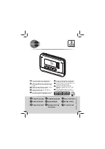
Instruction FH-CWD Thermostat

Summary of Contents for FH-CWD

Page 1: ...Instruction FH CWD Thermostat...

Page 2: ......

Page 3: ...2D Produced by Danfoss Floor Heating Hydronics 05 2011 Instruction FH CWD Thermostat Instruction FH CWD Thermostat 5 FH CWD 15 FH CWD Thermostat Gebrauchsanweisung 25 Instructions thermostat FH CWD 35...

Page 4: ...4 VI CU B2 2D Produced by Danfoss Floor Heating Hydronics 05 2011 Instruction FH CWD Thermostat...

Page 5: ...and floor temperature control 8 6 Maximum floor temperature protection 9 7 Frost protection 10 8 Error messages 10 9 Technical Specifications 11 10 Figures and illustrations 55 Index IMPORTANT Protect...

Page 6: ...onal Overview Front fig 1 Push button Push button M Up down selectors Back fig 2 Screw hole for flush mounting Terminals for cable mounting Symbols in the display fig 3 Room Sensor Floor Sensor Temper...

Page 7: ...ermostat fig 5 and fig 6 Remove the connection cable between front and back part Connect the thermostat correctly to mains supply according to the Wiring Diagram fig 6 Mount the thermostat by using th...

Page 8: ...d room tempera ture value is shown in the display When releasing the selector the display returns to actual room temperature 5 Choosing room temperature control or both room and floor temperature cont...

Page 9: ...excess heat For specific maximum floor tempera tures please refer to recommendations from floor suppliers Displaying the Floor Temperature The function allows you to check the internal tem perature of...

Page 10: ...ures The room temperature will be maintained around 5 C Turn OFF the thermostat by pressing Fig 1 Press M Fig 1 for 3 seconds and release Select 01 00 disabled If the room temperature is lower than 5...

Page 11: ...99 x 19mm Adjustment mode Push buttons Programmable No Fault indication failure mode If room sensor failure E1 will be displayed If floor sensor failor E2 will be displayed In any case thermostat wil...

Page 12: ...Yes LED indicator No Max load inductive 1A Max load resistive 3A Mounting Flush Mounting for Euro pean and Chinese built in sockets Network wire No Network wireless No Off set function Yes 10 C Power...

Page 13: ...ature Description Sensor floor Optional 2 terminals S1 S2 for external sensor mounting Sensor type NTC 10K accuracy 1 Sensor floor set range 20 45 C Sensor room NTC 100K accuracy 1 Sensor room set ran...

Page 14: ...14 VI CU B2 2D Produced by Danfoss Floor Heating Hydronics 05 2011 Instruction FH CWD Thermostat...

Page 15: ...15 VI CU B2 2D 05 2011 Danfoss FHH FH CWD 1 16 2 17 3 17 4 18 5 18 6 19 7 20 8 20 9 21 10 55...

Page 16: ...16 VI CU B2 2D 05 2011 Danfoss FHH FH CWD 1 1 2 3...

Page 17: ...17 VI CU B2 2D 05 2011 Danfoss FHH FH CWD 2 3 5 6 6 6 L L 85 250 50 60 NO NO NC NC N N 2 S2 S1...

Page 18: ...18 VI CU B2 2D 05 2011 Danfoss FHH FH CWD 4 1 3 1 5 1 1 10 01 1 01...

Page 19: ...19 VI CU B2 2D 05 2011 Danfoss FHH FH CWD 02 01 6 1 M 1 1...

Page 20: ...20 VI CU B2 2D 05 2011 Danfoss FHH FH CWD M 1 5 M 1 1 5 SET 7 5 C 1 M 1 3 01 00 5 C 7 C 00 8 E1 E2...

Page 21: ...21 VI CU B2 2D 05 2011 Danfoss FHH FH CWD E2 M 1 9 EN 60730 RAL 9016 86 x 99 x 19 E1 2 5 C 7 C 10 C 60 C...

Page 22: ...22 VI CU B2 2D 05 2011 Danfoss FHH FH CWD 1 C 1 C IP 30 1A 3A 10 C...

Page 23: ...23 VI CU B2 2D 05 2011 Danfoss FHH FH CWD 2 85 250 50 60 2 S1 S2 NTC 10K 1 20 45 C NTC 100K 1 5 35 C 94V0 ABS PC...

Page 24: ...24 VI CU B2 2D 05 2011 Danfoss FHH FH CWD...

Page 25: ...e Bodentemperatur 29 7 Frostschutz 30 8 Fehlermeldungen 31 9 Technische Spezifikationen 31 10 Abbildungen und Illustrationen 55 Stichwortverzeichnis WICHTIG Achten Sie darauf dass das Thermostat nicht...

Page 26: ...Abb 1 Druckknopf Druckknopf M Auf Ab Navigationstasten R ckseite Abb 2 Schraubloch f r Unterputz Anbringung Anschl sse f r Verkabelung Symbole auf der Anzeige Abb 3 Raumf hler Bodenf hler Temperatura...

Page 27: ...schlusskabel zwischen Vorder und R ckseite des Ger ts Schlie en Sie das Thermostat ordnungsgem an die Netzversorgung an siehe Schaltbild in Abb 6 Befestigen Sie das Thermostat mit den beiliegen den Sc...

Page 28: ...Standard angezeigt Einstellen der Raumtemperatur Abb 1 Dr cken Sie um die gew nschte Raum temperatur einzustellen In der Anzeige erscheint Wenn Sie loslassen erscheint in der An zeige wieder die tats...

Page 29: ...01 6 Schutzfunktion f r maximale Bodentemperatur Mit dieser Funktion k nnen Sie eine maximal zul ssi ge Bodentemperatur festlegen Dies ist beispielswei se sinnvoll wenn Sie Edelholzb den vor Hitzesch...

Page 30: ...en Sie oder Abb 1 um die ge w nschte maximale Bodentemperatur einzustellen Warten Sie f nf Sekunden bis das Thermostat aus dem SET Betrieb wechselt und schalten Sie es aus 7 Frostschutz Indem Sie das...

Page 31: ...stellung lautet 00 8 Fehlermeldungen E1 wird bei einer St rung des Raumf hlers angezeigt E2 wird bei einer St rung des Bodenf hlers angezeigt E2 wird gelesen wenn Sie M dr cken Abb 1 um die Bodentempe...

Page 32: ...ner St rung des Bodenf hlers wird E2 angezeigt In jedem Fall schaltet das Thermostat alle Relaisausg nge aus Frostschutz Ja wenn aktiviert 5 C Heizung ein 7 C Heizung aus Umgebungstem peratur 10 C 60...

Page 33: ...europ ische und chinesi sche Einbausteckdosen Netzwerk draht gebunden Nein Netzwerk drahtlos Nein Offset Funktion Ja 10 C Leistungsauf nahme 2 W Stromversorgung Akku Nein Stromversorgung Netz 85 250...

Page 34: ...eibung F hler Boden Optional 2 Anschl sse S1 S2 f r Anschluss eines externen F hlers F hlergenauigkeit NTC 10 K 1 F hler Boden Einstellbereich 20 45 C F hler Raum NTC 100 K Genauigkeit 1 F hler Raum E...

Page 35: ...les commandes de temp rature ambiante et du sol 38 6 Protection de la temp rature maximum du sol 39 7 Hors gel 40 8 Messages d erreur 41 9 Sp cifications techniques 41 10 Chiffres et illustrations 55...

Page 36: ...elle Avant fig 1 Bouton poussoir Bouton poussoir M S lecteurs haut bas Dos fig 2 Trou de vis pour montage encastr Bornes pour montage de c bles Symboles l cran fig 3 Capteur de pi ce Capteur de sol In...

Page 37: ...thermostat d ambiance fig 5 et fig 6 Retirer le c ble de raccordement entre la partie avant et l arri re Raccorder correctement le thermostat l alimenta tion principale selon le sch ma de c blage fig...

Page 38: ...Fig 1 Appuyer sur pour r gler la valeur choisie pour la temp rature ambiante s affiche l cran Lorsque le s lecteur est rel ch l cran revient la temp rature ambiante r elle 5 Choisir la commande de tem...

Page 39: ...rotection de la temp rature maximum du sol La fonction permet de r gler une temp rature de sol maximum autoris e pour par exemple prot ger les sols en bois v ritable des d g ts dus une chaleur excessi...

Page 40: ...le thermostat quitte le mode SET et s teigne 7 Hors gel Utiliser le mode hors gel plut t que de d sactiver compl tement le thermostat pour prot ger contre les dommages dus aux basses temp ratures La t...

Page 41: ...les cas toutes les sorties de relais seront d sactiv es 9 Sp cifications techniques Fonction Description Approbation Marquage CE EN 60730 Couleur Blanc RAL 9016 Dimensions 86 x 99 x 19 mm Mode de r gl...

Page 42: ...1 C Hyst r sis 1 C sym trique autour de la temp rature de r f rence Classe IP 30 R tro clairage LCD veilleuse Oui cran LCD Oui Indicateur DEL Non Charge max inductive 1A Charge max r sistive 3A Monta...

Page 43: ...gie Conserve les param tres en cas de coupure de courant Ils seront enregistr s sur une puce m moire Capteur sol 2 bornes S1 S2 en option pour le montage d un capteur externe Pr cision du type de capt...

Page 44: ...44 VI CU B2 2D Produit par Danfoss Floor Heating Hydronics 05 2011 Instructions thermostat FH CWD...

Page 45: ...45 VI CU B2 2D 05 2011 FH CWD 1 46 2 47 3 47 4 48 5 48 6 49 7 50 8 50 9 51 10 55...

Page 46: ...46 VI CU B2 2D 05 2011 FH CWD 1 1 M 2 3...

Page 47: ...47 VI CU B2 2D 05 2011 FH CWD 2 3 5 6 6 5 6 L L AC85 250V 50 60Hz NO NC N N 2 S2 S1...

Page 48: ...48 VI CU B2 2D 05 2011 FH CWD 4 1 3 1 5 1 1 10 01 1 01 02 01...

Page 49: ...49 VI CU B2 2D 05 2011 FH CWD 6 1 M 1 1 M 1 5 M 1 1 5...

Page 50: ...50 VI CU B2 2D 05 2011 FH CWD 7 5 1 M 1 3 01 00 5 7 00 8 E1 E2 M 1 E2...

Page 51: ...51 VI CU B2 2D 05 2011 FH CWD 9 CE EN 60730 RAL 9016 86 99 19mm E1 E2 5 7 10 60 1 1 0 5 IP 30 LCD LCD LED...

Page 52: ...52 VI CU B2 2D 05 2011 FH CWD 1A 3A 10 2W 85 250Vac 50 60Hz 2 S1 S2 NTC 10K 1 20 45 NTC 100K 1...

Page 53: ...53 VI CU B2 2D 05 2011 FH CWD 5 35 94V0 ABS PC...

Page 54: ...54 VI CU B2 2D Produced by Danfoss Floor Heating Hydronics 05 2011 Instruction FH CWD Thermostat...

Page 55: ...55 VI CU B2 2D Produced by Danfoss Floor Heating Hydronics 05 2011 Instruction FH CWD Thermostat 10 Figures and illustrations 10 10 Abbildungen und Illustrationen 10 Chiffres et illustrations 10...

Page 56: ...56 VI CU B2 2D Produced by Danfoss Floor Heating Hydronics 05 2011 Instruction FH CWD Thermostat Fig 1 Fig 2...

Page 57: ...57 VI CU B2 2D Produced by Danfoss Floor Heating Hydronics 05 2011 Instruction FH CWD Thermostat Fig 3 Fig 4...

Page 58: ...58 VI CU B2 2D Produced by Danfoss Floor Heating Hydronics 05 2011 Instruction FH CWD Thermostat Fig 5 Fig 6 FH CWD L NO NC N S2 S1 Remote Floor Sensor AC85 250V 50 60 Hz...

Page 59: ...59 VI CU B2 2D Produced by Danfoss Floor Heating Hydronics 05 2011 Instruction FH CWD Thermostat...

Page 60: ...www heating danfoss com...

Reviews: