


Danfoss ET1000 Crimp machine operator’s manual
AQ418954799548en-000101
© Danfoss ET1000 Crimp machine operator’s manual | 2022.06. | 3
Specifications and accessories
ET1000 Crimp machine and accessories
NOTE:
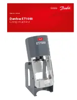
Your new crimp machine
has been calibrated and filled with
hydraulic oil in the factory. Do not
remove any plugs or caps until
necessary. Excess air in the hydraulic
system may cause erratic cylinder
movement during retraction. Refer
to the Setup and Assembly section
for instructions on removing air
from the hydraulic system.
Specifications
Crimper Dimensions:
22” tall x 16” width x 14” deep
Weight: 70 lbs. (machine & stand
only)
Pump Requirements:
• Reservoir Capacity:
36 cu. in (590 cc)
• Pressure Rating:
10,000 psi (690 bar)
• The air/hydraulic pump
requires a minimum of
100psi to operate at maxi-
mum efficiency.
Hose Production Capacity:
Crimps up to -16 in braided and spi-
ral hydraulic hose with core tooling
and up to -20 in braided hose using
non-core, specialty tooling.
Accessories
• Bench mount bracket
(Part # ET1000C-0001)
• Truck/wall mount bracket
(Part # ET1000C-0021)
• 1.5 oz. tube high efficiency
PTFE grease (
Part # T-400-G)
• 16 oz. can high efficiency
PTFE grease
(Part # FF91455)
• Handle kit includes 2 easy
grip handles with mounting
hardware
(Part # ET1187C-0028)
• Portability kit includes
2 easy grip handles with
mounting hardware, longer
hose assembly, and FF
series quick disconnect
couplings
(Part # ET1187C-0029)
Available pump options:
• Hand pump kit
(Part #ET1000PK-001)
• Air/hydraulic pump kit
(Part #ET1000PK-002)
• 110v electric pump kit
(Part #ET1000PK-003)
• 12v DC electric pump kit
(Part #ET1000PK-004)
Note: These pump kits include the pump,
connecting hose assembly, and all of the
adapters necessary to connect the pump to
the ET1000 crimp machine.
1.
Your new ET1000 crimp
machine comes disassembled
for ease of shipment. Before
use, the machine must be
assembled to the base with the
supplied quick release pins. Pins
should be installed from the
inside of the machine to avoid
any contact between the pins
and tooling during the crimping
process (See Figure A).
2.
Remove the plug from the top
cylinder port and install the
–06 size ORB,90 degree adapter
using 23-24 ft. lbs. assembly
torque. Orient the adapter so
that it points to the rear of the
crimp machine, away from the
operator.
3.
Install the pump connecting
hose assembly to the cylinder
adapter with the –06 size 37
degree swivel nut fittings using
18-20 ft. lbs. assembly torque.
4.
Do not exceed an 8” minimum
bend radius of the pump con-
necting hose when attaching the
hose to the pump and cylinder.
5.
If using your own pump, make
sure it has the requirements list-
ed in the Specifications section
above.
6.
Place the pump on the work
surface to either side of the
crimp machine. Install the 90
degree adapter to the pump
pressure port (Male NPTF threads
should be tightened following
the hex-marking procedure of 2
to 3 turns past hand tight).
7.
Remove excess air from the
hydraulic system. This can be
accomplished by placing the
pump at a higher level than the
cylinder and cycling the machine
approximately five times.
8.
Secure the machine frame to
a stable work surface using lag
screws or other suitable fasten-
ers.
Setup and Assembly
Hand pump
Air/hydraulic
pump
110v electric
pump
12v DC electric
pump
Figure A