


©Danfoss A/S (AC-MCI / sw), 2014-03
DKRCC.PS.RP0.A1.02/520H7142
9
8
DKRCC.PS.RP0.A1.02/520H7142
©Danfoss A/S (AC-MCI / sw), 2014-03
Manual Superheat controller type EKD 316
Manual Superheat controller type EKD 316
Installation
The EKD 316 is normally mounted on a DIN rail, and the necessary
connections are shown in the diagram. If the sensor S4 is not
used to measure air temperature in connection with thermostat
function or as part of the controlling loop, then it is not necessary
to connect the S4 sensor. The 18-24 V battery input at terminals 15
and 16 is not required if battery back-up is not needed.
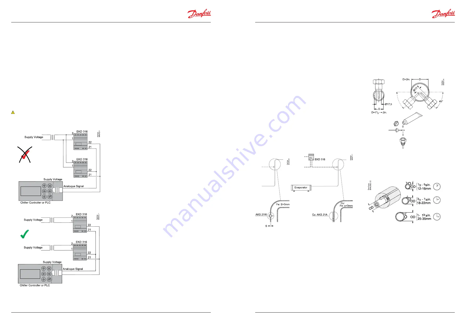
Power supply considerations
The terminals 1 and 2 for the voltage supply are not isolated
from the rest of the controller terminals. This means care should
be taken when connecting two or more controllers to the same
voltage supply. In the example below, the two controllers are
connected to the same voltage supply and on the input side,
terminals 21 (Analogue Input) are connected to each controller
and similarly terminals 22 (GND).
This way of connecting the controllers can cause damage and
should be avoided.
Note:
The same applies to other signal inputs e.g. terminals 2 and 4.
See warning page 5.
Stepper motor output
After installation the following checks can be made to the
connection between the EKD 316 controller and the stepper
motor of the ETS 6/ETS valve.
With the power off, check that resistance between terminals 5 and
6 and terminals 7 and 8 is approximately 53 Ohms. Make slight
allowances for cable resistance.
If resistance values differ from above, ensure that the cable is
properly connected to the actuator of the ETS 6/ETS valve.
With the power on and parameter o18 set to 1, measure the phase
current from terminal 5 (or 6) and terminal 7 (or 8 ) with a true RMS
multimeter when the valve is operating. The valve can be driven
from 0% to 100% and vice versa by changing the valve opening
percentage in parameter o45. The phase current should be 70 mA
rms when operating.
If this not the case and the cable connections are correct, then the
stepper motor driver in the EKD 316 might be damaged.
Remember to set o18 back to 0 after checks.
If checks 1) and 2) are not correct, ensure that motor cable
corrections are correct and the cable length is less than 30 meters.
Output relay contact
The contact of the alarm relay will be made when there is an alarm.
Battery back-up
A battery back-up can be connected to terminals 3 (+) and 4 (-).
The voltage should be at least 18 V and this can be achieved by
using two 9 V 100 mAh batteries in series.
The back-up voltage can also come from UPS giving 24 V.
If the controllers are operated by a common analogue signal as
above, the voltage supply should be separate as shown below.
Choice of S2 sensor type
Surface sensor S2 *
Suction pipe of copper or on thin (≤ 3mm) steel pipe.
Remember to put on heat conducting paste and insulate the
sensor.
Pocket sensor S2 **
Suction pipe of steel ≥ 3mm
*) Pt1000 Ω Type AKS21 or AKS10
**) Pt1000 Ω Type AKS21W
Installation sensors
S2 sensor positioning in the suction line
The position of the S2 sensor is crucial for an optimal control of the
liquid injection.
The main purpose is to measure temperature of the superheated
gas leaving the evaporator. In addition to this, the S2 sensor plays
an important role detecting fast changes of superheat. Suction
pressure is on the whole stable whereas the leaving gas condition
is dependent on the temporary mixture of gas, liquid refrigerant
and oil.
The sensor is also there to react quickly on liquid passing the
evaporator, to avoid damage to the compressor.
An S2 sensor placed two-thirds of the way up a riser after an oil
trap is where conditions are at their optimum, i.e. good mixture of
gas, oil and liquid droplets, provided this is not more than 0.5 m
from the evaporator.
If a horizontal pipe is the only option, the S2 sensor must be
placed at least half a meter away from the evaporator.
S1 (Po pressure) is less critical but must be close to the actual
suction pressure right after the evaporator.
If the measured value is 1-2 K lower than the actual value of Po
right after the evaporator, it may cause the evaporator to flood.
This is the case when the pressure transmitter is located in the
machine room away from the evaporator. If the measured value
is higher than the actual value of Po, the evaporator might be
starved of liquid.
AKS 21W
Heat compound
S2 sensor fixing on the suction pipe:
When the S2 sensor is fixed to the surface of the suction pipe, the
angle of the sensor position will depend on the diameter of the
pipe, as given in the following diagram: