Intelligent solutions with lasting effect
Visit devi.com
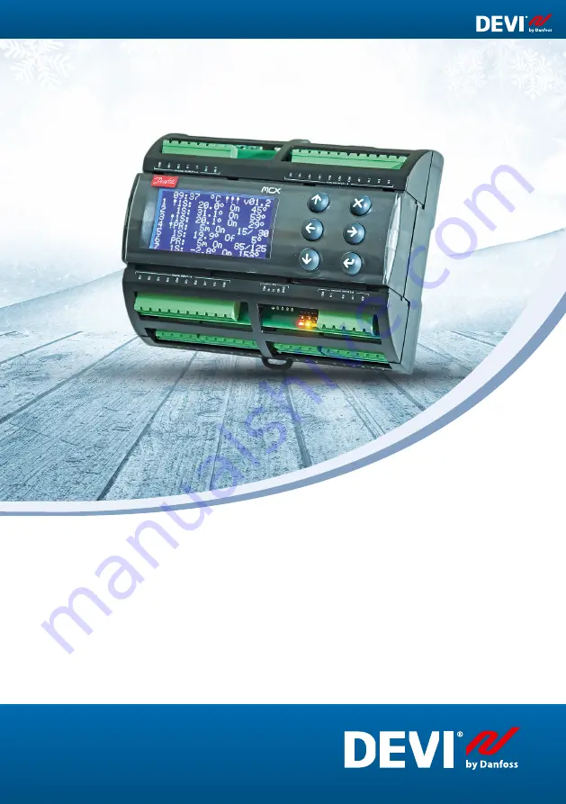
DEVIreg™ Multi
Installation and User Guide
7 channel DIN-rail programmable controller
EN
Page 1: ...Intelligent solutions with lasting effect Visit devi com DEVIreg Multi Installation and User Guide DEVIreg Multi 7 channel DIN rail programmable controller EN...
Page 2: ......
Page 3: ...et up 20 4 4 4 PR or Power Regulation mode 21 4 4 5 MOn and MOf Manually heating On and Manually heating Of mode 23 4 4 6 CableOK special channel function 24 4 4 7 Channel ON OFF special function 26 4...
Page 4: ...ctions can be set up for heating or cooling systems Additionally relay contacts are not connected to a voltage source inside the controller and can be used for control systems with any voltage up to 2...
Page 5: ...re to more than 35 C Note Product is designed for Over Voltage Category II When used in fixed installation installation must be equipped with transient protection 3 Mounting Instructions Please observ...
Page 6: ...emperature sensors including NTC 15 kOhm at 25 C This mode can be set up with special function to control Alarm min and max temperatures Additionally it can be set up with so called Cable OK function...
Page 7: ...Of Manually On Of control mode The mode with relay setting either for state Heating On or Heating Of and time setting during which this mode will be performed Heating On Heating Of The state when cont...
Page 8: ...hannel When Active Yes Channel s algorithm works according to the settings and data is displayed on the screen s When it s not Active or Active No Channel does not work at all and empty line appears o...
Page 9: ...lding s mechanical and electrical equipment such as ventilation lighting power systems fire systems and security systems RS 485 RS 485 or RS485 also known as TIA 485 A or EIA 485 is a standard definin...
Page 10: ...lect go to the Main menu Besides the normal function of the buttons some special combinations are important to the user For quick changing of any values e g temperature hold button Up or Down Return t...
Page 11: ...the 1st display line and the Channel 1 7 data are visible on the lines from 2 to 8 This view gives the user an example of all Channels on one screen Main sub screens view These screens give to user q...
Page 12: ...ssing Escape button from Main Screen screen s with Alarm appears If more than 1 Alarm is happened use navigation by going Up Down Pressing Escape button again leads from Alarm to Main Screen Menu syst...
Page 13: ...tton you ll get to the bottom part of Main Menu Menu windows above display the root directory of the menu tree or so called Main Menu Activating any line by Enter button leads to a transition to a low...
Page 14: ...7 Line with mode Manually Of over mode PR with the remaining time in 57 min Line with mode Manually On over mode 1S with the remaining time in 133 min Line with mode PR with set up cycle time 180 min...
Page 15: ...od or MOn and MOf no sensor input one relay output Together with any control mode could be set up or enabled disabled some special functions and statuses Relay status RO RC CableOK Relay test 5 30 Cha...
Page 16: ...nu Channels settings Activate channels Activate X1 Enter Up Down YES NO Enter 2 1 here and further X means any Channel number in diapason from 1 to 7 2 here and further brackets indicate more detailed...
Page 17: ...rol because cooling is system having opposite algorithm to heating system The special setting for logical status Heating On is named Relay status RO RC Relay Opened RO or Relay Closed RC each Channel...
Page 18: ...t up mandatory control temperature optionally hysteresis and control alarm temperature diapason Temperature 1S mode has temp setting with max diapason from 50 C degree to 200 C Default 5 C NB Each typ...
Page 19: ...ler user to set correct alarm values that correspond to the sensor type and for the specific application to avoid overheating of the cable building materials and so on Example of data for Temp Alarm s...
Page 20: ...5 C NTC5k 5 kOhm 25 C NTC2k 2 kOhm 25 C NTC100 100 kOhm 25 C NTC16k 16 7 kOhm 100 C PT1000 1000 Ohm 0 C Ni100 100 Ohm 0 C Setting of Sensor type can be done by the following menu sequence EN Main Scre...
Page 21: ...Power Regulation mode Power regulation is time proportional power regulation mode with a simple duty cycle generator with time set up during which heating is turned on within the period This mode can...
Page 22: ...ating On Heating On Heating Off Heating Off Heating Off Heating On Period Period Common Channel scheme for PR mode is shown on the picture below Channel 1 COM DI 1 C 1 NO 1 AI 1 Two control parameters...
Page 23: ...ting time period during which heating will be turned on or turned off This mode can be started only on the base of 1S or PR mode and after Manually On Of mode is finished controller returns to the sam...
Page 24: ...proper functioning of the heating cable or other electrical equipment using a current flow control In other words the current in the heater is controlled when the heating is turned on Channel Alarm a...
Page 25: ...or Disabled Dis for any Channel By default Disabled CableOK NO NC Setting for state of digital input DI when CableOK function is OK It means if chosen NO for CableOK OK then digital input is not conn...
Page 26: ...up with status OFF or ON OFF means that there is no need to carry out Channel control algorithm due to for example a malfunction of the cable or sensor heating system installation and so on In other w...
Page 27: ...tive Channels show real sensor temperature and for PR mode show real time Additionally it is possible to do change any settings Settings Device ON OFF function can be done by the following menu sequen...
Page 28: ...roller can be set up with status OFF by mechanical switch connected to DI8 Alarm NC 8 DI 8 C 8 NO 8 COM DI 5 8 OFF ON Dev ice NB When no switch is used it means Device is always ON When Device is OFF...
Page 29: ...nter to Main Menu Channels settings Channel X Relay Test 5 30 sec Enter STOP START EN Main Screen Enter to Main Menu Channels settings Channel X Relay Test 5 30 sec Enter STOP START NB When this funct...
Page 30: ...screen Additionally any Alarm happening in the controller appears on the Main Screen like device Alarm with three exclamation symbols on the 1st line of the Main Screen Example is shown on the pictur...
Page 31: ...on can be found in two ways The simplest way to see Relay On cycles in total can be done by sequence EN Main Screen Up EN Main Screen Up For example the screen view can be as below The second way to s...
Page 32: ...by the following menu sequence EN Main Screen Enter to Main Menu Device settings Date Time setup Enter Right Left Enter YYYY MM DD WD hh mm ss EN Main Screen Enter to Main Menu Device settings Date Ti...
Page 33: ...3 C 3 NO 3 DI 4 NC 4 C 4 NO 4 DI 5 C 5 NO 5 DI 6 C 6 NO 6 DI 7 NC 7 C 7 NO 7 NC 8 DI 8 C 8 NO 8 COM DI 5 8 AI 1 COM AI 2 COM AI 3 4 AI 3 AI 4 COM AI 5 8 AI 5 AI 6 AI 7 D D GND I I I I I I I Power 110...
Page 34: ...i100 100 Ohm 0 C Sensor failure monitoring Disconnected or short circuited sensor Digital inputs DI1 DI8 voltage free contacts on off inputs Connection specification Grouped screws plug in connectors...
Page 35: ...Installation and User Guide DEVIreg Multi FEC Produced by Danfoss 35 6 2 Dimensions 110 140 60 63...
Page 36: ...Installation and User Guide DEVIreg Multi FEC Produced by Danfoss 36 7 Disposal Instruction...
Page 37: ...ment provides general indications for the setup of RS 485 networks A3 Modbus parameters and variables Modbus parameters and variables for DEVIreg Multi controller LABEL DESCRIPTION MIN MAX VALUE TYPE...
Page 38: ...00 0 32000 0 W RW 3018 Q8 Channel 1 Manually On Of P12 1 Manually On Of Time Set up period of time for MOn or MOf status max 900 minutes 1 900 1 min RW 3019 P13 1 Status On or Of for mode Heating Manu...
Page 39: ...n Of Start or Stop control mode Caution this mode may cause overheating and damage 0 1 0 STOP Enum 6 RW 3039 W9 Channel 2 Channel ON OFF O15 2 Channel ON OFF If OFF symbol in the line algorithm is sto...
Page 40: ...3 Sensor type I17 3 Sensor type 0 7 1 PT1000 Enum 9 RW 3059 R12 Channel 3 Relay Status RO RC I18 3 Relay status Set up Relay Opened RO or Relay Closed RC for status Heating On 0 1 0 RC Enum 10 RW 306...
Page 41: ...tching for 30 sec 0 1 0 STOP Enum 6 RW 3079 H1 Channel 5 Regulation Type Y1 5 Regulation Type 1S Single Sensor PR Power Regulation 0 1 1 1S Enum 1 RW 3080 H2 Channel 5 Temp Hysteresis Y2 5 Set Tempera...
Page 42: ...Channel 6 On Time Period T4 6 Set On Time 1 0 15 min RW 3101 T5 6 Set PR Period max 900 minutes 0 900 30 min RW 3102 Z4 Channel 6 Alarm Temps En Dis T6 6 Alarm Temp En Dis 0 1 0 Dis Enum 5 RW 3103 T7...
Page 43: ...bleOK En Dis Enable or Disable the function of current monitoring in the load 0 1 0 Dis Enum 5 RW 3124 V10 7 CableOK NO NC Set up DI7 status Normally Opened NO or Normally Closed NC when cable is OK 0...
Page 44: ...Alarm Sensor 7 0 1 AUTO ACTIVE Read 1901 15 E09 Alarm CableOK 1 0 1 AUTO ACTIVE Read 1901 00 E10 Alarm CableOK 2 0 1 AUTO ACTIVE Read 1901 01 E11 Alarm CableOK 3 0 1 AUTO ACTIVE Read 1901 02 E12 Alar...
Page 45: ...00 0 PT1000 Read 18507 7 Temperature7 50 0 200 0 PT1000 Read 18508 8 DI DIGITAL INPUTS 1 Cable1 0 1 N O Read 17504 2 Cable2 0 1 N O Read 17505 3 Cable3 0 1 N O Read 17506 4 Cable4 0 1 N O Read 17507 5...
Page 46: ...nt heaters Power supply units for thermostats All related accessories including heating cables and heating mats accessories Should you against all expectations experience a problem with your DEVI prod...
Page 47: ...The DEVIwarranty is granted to Name Address Postal code Phone Please observe In order to obtain the DEVIwarranty the following must be carefully filled in See other conditions on previous page Electr...
Page 48: ...08097125 AN335045092882en 000104 Produced by Danfoss 06 2020 Installation and User Guide DEVIreg Multi Danfoss A S Nordborgvej 81 6430 Nordborg Syddanmark Denmark...