© Danfoss | 2023.03
180R9346 | AQ240486503020en-001702 | 1
hpp.danfoss.com
Operation guide
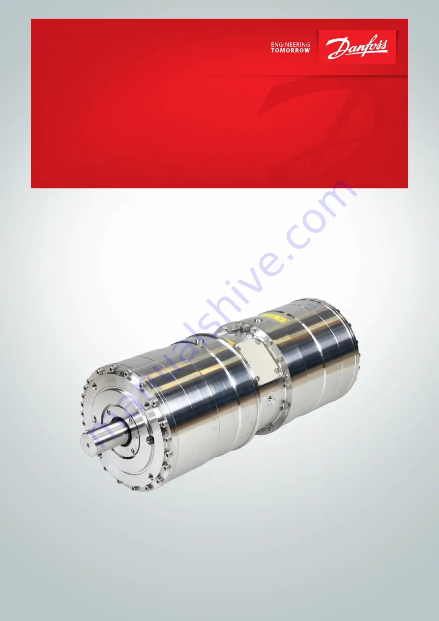
APP pumps with FDA approved seals
APP 53 / APP 65 / APP 78 / APP 86 / APP 92
Installation, Operation and
Maintenance Manual
Page 1: ...Danfoss 2023 03 180R9346 AQ240486503020en 001702 1 hpp danfoss com Operation guide APP pumps with FDA approved seals APP 53 APP 65 APP 78 APP 86 APP 92 Installation Operation and Maintenance Manual...
Page 2: ...quirement 8 3 8 Filtration 8 3 9 Properties of water 8 3 10 Air bubbles 8 3 11 Chemicals 8 4 Arrival inspection transportation handling lifting and storage 8 4 1 Arrival inspection 8 4 2 Warning 8 4 3...
Page 3: ...the pump onto the electric motor 14 7 7 Getting the pump unit back into operation 14 7 8 Storage of the pump 14 8 Troubleshooting and scrapping criteria 15 8 1 General safety information 15 8 2 Opera...
Page 4: ...type an serial number or higher Type Serial no APP 53 XXXXXX08 XXX APP 65 XXXXXX08 XXX APP 78 XXXXXX08 XXX APP 86 XXXXXX08 XXX APP 92 XXXXXX08 XXX The serial number is referring to the Serial no on t...
Page 5: ...nit mechanical and electrical parts Decommissioning the pump unit The pump must always be installed and used in accordance with existing national local sanitary safety regulations and laws It is the r...
Page 6: ...c motor if the motor is not designed for VFD operation This can damage the motor and cause unintended breakdown Danger Installation and maintenance must always take place during complete shutdown in a...
Page 7: ...allowable starting torque 3 5 Noise and vibration Noise level for a pump unit with a standard motor measured according to EN ISO 3744 2010 see appendix 1 Data sheet Possibilities to reduce noise and v...
Page 8: ...d from both the low pressure and high pressure side before the RO system is pressurised Special consideration should be given in order to minimize air bubbles in the feed flow Air bubbles can cause ca...
Page 9: ...of the mass varies from pump pump unit size to pump pump unit See below examples of where to not to attach the lifting slings on the pump unit with motor Correct lifting with 2 separate slings Wrong...
Page 10: ...irt or rust is not removed the pump and the valves can be damaged In worst case the pump can be damaged beyond repair 5 3 Fluid temperature Before start up the fluid and pump housing temperature must...
Page 11: ...c turers instruction CP12 Ensure all pipings have been flushed and are correct installed CP13 Check piping for possible air gaps 5 7 Lifting and positioning Lift the pump unit onto base Remember vibra...
Page 12: ...y circuit breaker Start the motor for 1 second and observe the direction of rotation either looking at the fan of the motor or the coupling through the inspection hole in the bell housings not availab...
Page 13: ...d for inspection as recommended it can lead to damage of the pump or break down See also service and warranty section in the appendix 1 Data sheet in appendix 2 Instruction or appendix 4 Instruction f...
Page 14: ...he pump according to the Disassembling and Assembling Instruction available at hpp danfoss com Clean all parts and surfaces with a fluid compatible with the materials found in the pump Wipe the parts...
Page 15: ...ooding which can cause slipping tripping or falling If water is leaking into the electric motor it can cause electric shock fire short circuit or even death When mounting the pump vertically always mo...
Page 16: ...16 180R9346 AQ240486503020en 001702 Danfoss 2023 03 Operation guide Installation Operation and Maintenance APP 53 92 pumps...
Page 17: ...180R9346 AQ240486503020en 001702 17 Danfoss 2023 03 Operation guide Installation Operation and Maintenance APP 53 92 pumps hpp danfoss com...
Page 18: ...Appendices 17 1 Data sheet for APP pumps 53 92 AI167386503010en 001301 19 2 Instruction for APP pumps 53 92 180R9368 43 3 Electric motors 180R9230 55 4 Bowex coupling manual 61 5 Recommended service...
Page 19: ...Danfoss 2023 03 180R9346 AQ240486503020en 001702 1 Data sheet APP Pumps APP 53 APP 65 APP 78 APP 86 hpp danfoss com...
Page 20: ...ves 29 6 1 APP 53 92 integrated flushing valve 29 7 Motor requirements 29 7 1 Calculation factor at 60 barg 870 psig for APP 53 92 29 8 Temperature and corrosion 30 8 1 Operation 30 9 Installation 30...
Page 21: ...750 stainless steel and carbon reinforced PEEK Certified quality Available with positive material idenfication PMI certification on request ISO 9001 ISO 14001 IAFT 16949 ATEX certification available f...
Page 22: ...73 73 Max inlet pressure peak barg 10 10 10 10 10 psig 145 145 145 145 145 Min outlet pressure barg 30 30 30 30 30 psig 435 435 435 435 435 Speed Min speed continuous rpm 700 700 700 700 700 Max speed...
Page 23: ...NEMA motors 4 pole current insulated ND non drive end bearing 6 Operating with water Pump size APP 53 1500 APP 65 1500 APP 78 1500 APP 86 1700 APP 92 1780 Code number 180B7806 180B7807 180B7808 180B78...
Page 24: ...s diagram shows that the flow can be changed by changing the rotation speed of the pump The flow rpm ratio is constant and the required flow can be obtained by changing the rotation speed to a corresp...
Page 25: ...ntenance APP 53 92 pumps 5 2 APP 65 flow at different rpm 20 00 25 00 30 00 35 00 40 00 45 00 50 00 55 00 60 00 65 00 70 00 75 00 80 00 85 00 90 00 Flow m3 h Speed RPM 100 00 120 00 140 00 160 00 180...
Page 26: ...ntenance APP 53 92 pumps 5 3 APP 78 flow at different rpm 20 00 25 00 30 00 35 00 40 00 45 00 50 00 55 00 60 00 65 00 70 00 75 00 80 00 85 00 90 00 Flow m3 h Speed RPM 100 00 120 00 140 00 160 00 180...
Page 27: ...ntenance APP 53 92 pumps 5 3 APP 86 flow at different rpm 20 00 25 00 30 00 35 00 40 00 45 00 50 00 55 00 60 00 65 00 70 00 75 00 80 00 85 00 90 00 Flow m3 h Speed RPM 100 00 120 00 140 00 160 00 180...
Page 28: ...PP 53 92 pumps 5 4 APP 92 flow at different rpm 20 00 25 00 30 00 35 00 40 00 45 00 50 00 55 00 60 00 65 00 70 00 75 00 80 00 85 00 90 00 95 00 100 00 Flow m3 h Speed RPM 100 00 120 00 140 00 160 00 1...
Page 29: ...Required power kW or kW or Calc factor Calc factor Calc factor 1 hp 0 75 kW 1 gpm 3 79 l min 1 m3 h 4 40 gpm 1 kW 1 34 hp 1 l min 0 26 gpm 1 gpm 0 23 m3 h Name rpm Calculation factor APP 53 1500 528 A...
Page 30: ...esh water at operation stop in order to minimize the risk of crevice corrosion 8 Temperature and corrosion 316L Super Duplex 80 C 70 60 50 40 30 20 100 160 1600 1000 16000 10 000 160000 100 000 CI ppm...
Page 31: ...ibrations than low rpm because of higher frequency Discharge pressure High pressure generates more noise than low pressure Pump mounting Rigid mounting generates more noise than flexible mounting beca...
Page 32: ...s the Danfoss APP pump begins to create pressure and flow immediately after start up and regardless of any counter pressure a safety or pressure relief valve 8 should be installed after the non return...
Page 33: ...180R9346 AQ240486503020en 001702 33 Danfoss 2023 03 Operation guide Installation Operation and Maintenance APP 53 92 pumps 10 1 APP 53 10 Dimensions and connections...
Page 34: ...34 180R9346 AQ240486503020en 001702 Danfoss 2023 03 Operation guide Installation Operation and Maintenance APP 53 92 pumps 10 2 APP 65 92 APP 65 92...
Page 35: ...ee typical installations with check valve VCM 92 mounted in the outlet port in the drawing below Non standard configurations are available on request For adjustment on site please see Installation Ope...
Page 36: ...180R9346 AQ240486503020en 001702 Danfoss 2023 03 Operation guide Installation Operation and Maintenance APP 53 92 pumps 10 3 APP 53 92 with IE3 motor IEC 315S 4 10 4 APP 53 92 with IE3 motor IEC 315M...
Page 37: ...9346 AQ240486503020en 001702 37 Danfoss 2023 03 Operation guide Installation Operation and Maintenance APP 53 92 pumps 10 5 APP 53 92 with IE3 motor IEC 315L 1 4 10 6 APP 53 92 with IE3 motor IEC 315L...
Page 38: ...aulic 1 B Length C Material Max Pressure Code number 3 Inlet connector 87 8 mm 3 46 inch 3 Vic OSG 61 0 mm 2 40 Super Duplex 10 barg 145 psig 180Z1991 3 outlet connector 87 8 mm 3 46 inch 3 Vic OSG 65...
Page 39: ...r Use only Style 77DX coupling or equivalent 12 VCM 3 Victaulic Type Connection1 Diameter mm inch Victaulic 3 outlet connection Length mm inch Material22 Max pressure barg psig Code number VCM 92 3 ou...
Page 40: ...r Duplex 5 Spring Hasteloy 6 O ring NBR 7 O ring FKM 75 8 O ring NBR 12 2 Flow versus pressure Pressure drop curves for check valve VCM 92 0 0 05 0 1 0 15 0 2 0 25 0 3 0 35 0 4 0 45 0 5 20 25 30 35 40...
Page 41: ...n order to prevent a potential breakdown of the pump If the parts are not replaced more frequent inspection is recommended according to our guidelines Pump shutdown The APP pumps are made of Duplex Su...
Page 42: ...Danfoss DCS SGDPT SI 2023 03 42 180R9346 AQ240486503020en 001702 Operation guide Installation Operation and Maintenance APP 53 92 pumps AI167386503010en 001301...
Page 43: ...Danfoss 2023 03 180R9346 AQ240486503020en 001702 1 hpp danfoss com Instruction APP Pump Instruction APP 53 APP 65 APP 78 APP 86 APP 92...
Page 44: ...ilding up the pump unit with BoWex coupling 46 3 1 Assembly of the coupling 46 3 2 Alignment between the motor and pump shaft 46 3 3 Overall assembly with coupling BoWex ELASTIC type HEW compact 47 3...
Page 45: ...le hoses 4 to minimize vibrations and noise 5 In order to eliminate the risk of damage and cavitation a positive pressure at the inlet 5 is always to be maintained at min inlet pressure and max inlet...
Page 46: ...prove component performance Therefore it is important that the inlet water is filtered properly to minimize the wear of the pump The main filter must have a filtration efficiency of 99 98 at 10 m We r...
Page 47: ...HEW Compact Coupling See the Coupling Manual from BoWex 3 3 Overall assembly with coupling BoWex ELASTIC type HEW compact Component Quantity Description 1 1 Elastomer part 2 1 Hub 4 1 Coupling flange...
Page 48: ...ocking screws Measure the distance a from the end of the bell housing to the end of the toothing of the coupling 4 Mount the coupling on motor shaft without using hammer If needed then polish motor sh...
Page 49: ...tton of coupling claw 4 Mount the coupling on motor shaft Ensure the coupling and motor flange are not in contact with each other 5 Measure from motor flange to the top of the coupling That measuremen...
Page 50: ...desired please contact Danfoss High Pressure Pumps Choose proper tolerances to ensure an easy mounting of the elastic coupling without use of tools Please take care to observe the recommended length t...
Page 51: ...bleeding plug see item 3 5 using an allen key only plugs with internal hexagon sockets Retighten the plug when water appears from the bleeding plug 4 Make sure that the direction of rotation of the el...
Page 52: ...must always be connected to the water supply in order to avoid damage if it should run dry 6 4 Disconnection If the inlet line is disconnected from the water supply the pump will be emptied of water...
Page 53: ...bleeding and venting Running the pump at speed outside specifications Supplying the pump with water at temperature higher than recommended Running the pump at inlet pressure outside specifications Ru...
Page 54: ...Danfoss DCS SGDPT SI 2023 03 54 180R9346 AQ240486503020en 001702 Operation guide Installation Operation and Maintenance APP 53 92 pumps 180R9368 AN220686503013en 000901...
Page 55: ...M a n u a l Electric Motors Motor Manual hoyermotors com...
Page 56: ...forces It is important to ensure that the mounting conditions do not cause resonance with the rotational frequency and the doubled supply frequency Only mount or remove drive components pulley couplin...
Page 57: ...ed motors are half of the above values The table values are based on an ambient temperature of 25 C The values must be halved for every 15K increase in bearing temperature Higher speed operations e g...
Page 58: ...1702 Danfoss 2023 03 Operation guide Installation Operation and Maintenance APP 53 92 pumps Connection diagram Anschlu diagram Anslutningdiagramm Forbindelsesdiagram Aansluitdiagram Connection Conexi...
Page 59: ...180R9346 AQ240486503020en 001702 59 Danfoss 2023 03 Operation guide Installation Operation and Maintenance APP 53 92 pumps...
Page 60: ...chen T 49 89 700 88 235 F 49 89 543 56 333 germany hoyermotors com hoyermotors com Sweden Liljeholmsstranden 5 PO box 44017 SE 100 73 Stockholm T 46 8 446 877 13 sweden hoyermotors com hoyermotors com...
Page 61: ...ISO 16016 Drawn 2017 04 24 Shg Hk Replacing KTR N dated 2013 06 10 Verified 2017 04 24 Shg Replaced by BoWex ELASTIC highly flexible flange coupling type HEW1 HEW2 and their combinations according to...
Page 62: ...tion 6 2 2 General advice 6 2 3 Safety and advice symbols 7 2 4 General hazard warnings 7 2 5 Intended use 7 2 6 Reference to EC Machinery Directive 2006 42 EC 8 3 Storage transport and packaging 8 3...
Page 63: ...158 110 80 125 125 125 192 438 15 16 M12 416 478 175 140 99 G 125 125 125 192 489 8 M12 440 530 175 140 95 150 160 160 225 542 9 6 M16 470 585 225 150 100 G 150 160 160 225 542 9 6 M16 504 585 225 15...
Page 64: ...00 80 40 T40 750 2250 G 150 T40 7000 21000 50 T50 950 2850 T50 9200 27600 65 T65 1200 3600 T65 11500 34500 G 80 40 T40 1250 3750 200 T40 9500 28500 50 T50 1600 4800 T50 12500 37500 65 T65 2000 6000 T6...
Page 65: ...575 1725 173 9500 1 2 5 2 1240 80 T50 900 2700 270 4400 96 48 24 5000 0 6 10 5 420 T65 1100 3300 330 13000 0 8 7 9 1090 T70 1300 3900 390 16500 1 2 5 2 1450 100 T50 2000 6000 600 3200 156 78 39 17000...
Page 66: ...or the particular application see catalogue drive technology BoWex ELASTIC If the operating conditions performance speed modifications on engine and machine change the coupling selection must be revie...
Page 67: ...cidental switch on You may be seriously hurt by ro tating parts Please make absolutely sure to read through and observe the following safety indications All operations on and with the coupling have to...
Page 68: ...enerating devices like e g fluorescent light sources mercury vapour lamps or electrical high voltage appliances Humid storage rooms are not suitable Please make sure that condensation is not generated...
Page 69: ...4762 7 2 Setscrews DIN EN ISO 4029 Illustration 9 BoWex ELASTIC type HEW Compact Components of BoWex ELASTIC type HEW ZS Component Quantity Description 1 1 Elastomer part 2 1 Hub spec 3 1 Intermediate...
Page 70: ...an end plate to fasten the hub or coupling flange axially Illustration 12 Concentricity and axial runout The customer bears the sole responsibility for all machining processes performed subse quently...
Page 71: ...ing dimensions L LHEW1 LHEW2 or LHEW ZS Disregarding this advice may cause damage to the coupling Applies with type HEW ZS only size 100 to G 125 Screw the flange hub component 4 2 with the additional...
Page 72: ...20 250 If used in potentially explosive atmospheres the setscrews to fasten the hubs as well as all screw connections must be secured against working loose additionally e g conglutinating with Loctite...
Page 73: ...see illustration 14 The displacement figures specified are general standard figures that apply up to an ambient temperature of 80 C ensuring a sufficient service life of the BoWex ELASTIC coupling Di...
Page 74: ...with n 1500 rpm Kw 40 3 1 0 1 0 1 0 1 0 1 0 1 0 1 0 1 0 50 3 0 75 0 75 0 75 0 75 0 75 0 75 0 75 0 75 65 2 3 0 5 0 5 0 5 0 5 0 5 0 5 0 5 0 5 Perm angular displace ment with n 3000 rpm Kw 40 3 0 5 0 5...
Page 75: ...ng rings NBR can be used as connecting element between pump and electric motor The cover may only be taken off with standstill of the unit If the couplings are used in locations subject to dust explos...
Page 76: ...d Components are mixed up by mistake assembled incorrectly No original KTR components purchased parts are used Old already worn out elastomer parts or those stored for too long are used The coupling u...
Page 77: ...e the coupling and remove remainders of the elastomer part 3 Inspect coupling components and re place coupling components that are damaged 4 Insert elastomer part assemble coupling components 5 Inspec...
Page 78: ...regarding the use in potentially explosive atmospheres Type HEW1 and HEW2 hub elastomer coupling flange Annex A applies for BoWex ELASTIC HEW1 and HEW2 only Conditions of operation in potentially exp...
Page 79: ...up of the coupling If you note insignificant or no wear on the elastomer part upon this initial inspection further inspections can each be performed after 6000 operating hours or at the latest after...
Page 80: ...urn the hub in the direction of drive and measure the torsional backlash Smax When reaching the torsional backlash Smax the elastomer part must be replaced Illustration 16 Marking of the elastomer par...
Page 81: ...5 65 1 4 2 5 G 125 2 0 3 5 80 1 6 2 7 150 2 0 3 5 G 80 1 6 2 7 The ATEX marking of the BoWex ELASTIC coupling is done on the polyamide flange of the elastomer specifying the following details Short la...
Page 82: ...b of directive 2014 34 EU and comply with the general safety and health re quirements according to enclosure II of directive 2014 34 EU The BoWex ELASTIC complies with the specifications of directive...
Page 83: ...180R9346 AQ240486503020en 001702 83 Danfoss 2023 03 Operation guide Installation Operation and Maintenance APP 53 92 pumps...
Page 84: ...Danfoss DCS SGDPT SI 2023 03 84 180R9346 AQ240486503020en 001702 Operation guide Installation Operation and Maintenance APP 53 92 pumps...
Page 85: ...Danfoss 2023 03 180R9346 AQ240486503020en 001702 1 Instruction APP pumps APP 53 92 Recommended service intervals hpp danfoss com...
Page 86: ...urs 125 1 Cover flange for shaft seal Super Duplex No wear part No wear part 93 8 Back up ring PTFE 24 000 hours 24 000 hours O ring overall NBR 24 000 hours 24 000 hours Screw overall AISI 316 24 000...
Page 87: ...ced The pictures below is ment as a guideline for evaluating the wear of the sliding surface Cavitation of the piston shoes New inspection is required in 3 000 4 000 hours Cavitation of the piston sho...
Page 88: ...Danfoss DCS SGDPT SI 2023 03 88 180R9346 AQ240486503020en 001702 Operation guide Installation Operation and Maintenance APP 53 92 pumps AX281930801330en 000401...
Page 89: ...Danfoss 2023 03 180R9346 AQ240486503020en 001702 1 Parts list APP Pumps APP 53 APP 65 APP 78 APP 86 APP 92 hpp danfoss com...
Page 90: ...and Maintenance APP 53 92 pumps Table of Contents 1 Validity 91 2 Parts list APP 53 92 serial no 07 or higher 92 3 Exploded view APP 53 92 serial no 07 or higher 94 4 Parts list APP 53 86 serial no up...
Page 91: ...nance APP 53 92 pumps This Parts list contains two part list tables for serial numbers 07 and higher and up to 06 The serial no is referring to the Serial no on the product label The digits shown 08 i...
Page 92: ...30x3 A4 0031 1 Swash plate APP 53 non drive end 1 4410 x 0031 1 Swash plate APP 65 non drive end 1 4410 x 0031 1 Swash plate APP 78 92 non drive end 1 4410 x 0032 1 Swash plate APP 53 drive end 1 4410...
Page 93: ...180B4559 APP 53 92 Cylinder barrel kit 180B4649 APP 53 92 Port flange kit 2 Pos Qty Description Material 0121 1 Center flange APP H 1 4462 x 0122 1 O ring 80 0 x 2 mm NBR x 0124 1 Shaft seal NBR x 01...
Page 94: ...94 180R9346 AQ240486503020en 001702 Danfoss 2023 03 Operation guide Installation Operation and Maintenance APP 53 92 pumps 3 Exploded view APP 53 92 serial no 07 or higher...
Page 95: ...P 65 non drive end 1 4410 x 0031 1 Swash plate APP 78 86 non drive end 1 4410 x 0032 1 Swash plate APP 53 drive end 1 4410 x 0032 1 Swash plate APP 65 drive end 1 4410 x 0032 1 Swash plate APP 78 86 d...
Page 96: ...Description Material 0121 1 Center flange APP H 1 4462 0122 1 O ring 80 0 x 2 mm NBR x 0124 1 Shaft seal NBR x 0125 1 Cover for shaft seal 1 4462 0126 4 Pin 10 5 x 20 1 4410 x x x 0127 4 Screw M6 x 12...
Page 97: ...180R9346 AQ240486503020en 001702 97 Danfoss 2023 03 Operation guide Installation Operation and Maintenance APP 53 92 pumps 5 Exploded view APP 53 86 serial no up to 06 220 Nm 22 Nm...
Page 98: ...nbraco 1 M8 x 70 full thread Unbraco 3 Valve plate fixation device 3 Tool bracket 1 Tool washer 2 M16 pin 1 Nut M16 A4 4 17 30 x 3 washer 1 Screw M8 x 40 A4 80 1 Valve plate mount 1 24 mm 1 2 socket 1...
Page 99: ...180R9346 AQ240486503020en 001702 99 Danfoss 2023 03 Operation guide Installation Operation and Maintenance APP 53 92 pumps...
Page 100: ...Danfoss DCS SGDPT SI 2023 03 100 180R9346 AQ240486503020en 001702 Operation guide Installation Operation and Maintenance APP 53 92 pumps AX191786502906en 001201...
Page 101: ...Danfoss 2023 03 180R9346 AQ240486503020en 001702 1 Service guide Trouble shooting guide APP APP S and APP S 674 pumps hpp danfoss com...
Page 102: ...e of contents Table of Contents Table of contents 102 Trouble shooting fish bone chart 103 1 No flow no pressure 104 2 Reduced flow reduced pressure 105 3 High torque on electric motor 106 4 Noise fro...
Page 103: ...ent 2 1 6 Main filtration 2 1 Wear in pump internal leakage 2 1 7 Fluid type 2 1 8 High fluid temperature 4 1 Air in fluid 4 2 Bleeding conditions of pump 4 3 Min max nominal inlet pressure 4 4 Pump r...
Page 104: ...Check that the monitor switches are working correctly 1 3 7 Disconnect pump from electric motor and check that the motor is capable of running with no load If motor type relay or the electrical fuse...
Page 105: ...is very worn The filters can be bypassed even if they are correctly mounted Some filters can create channelling where particles can pass through the filter in tunnels String wounded filters are typica...
Page 106: ...resulting in higher motor torque 3 2 Pump starts against pressure 3 2 1 Check that electric motor is correctly sized 3 2 2 Check internal parts see item 2 1 3 2 3 Systems with more than one electric...
Page 107: ...ached 4 4 Pump reversing 4 4 1 Dismantle pump and check if anything is broken or worn See 1 No flow item 1 2 Pump reversing WARNING The pump must not run without water for more than a few seconds If t...
Page 108: ...e too fast flow turbulence through the pipes and thus increase the noise level 5 3 Hose stiffness 5 3 1 Use a more flexible hose Danfoss can provide flexible hoses Please contact Danfoss High Pressure...
Page 109: ...surface Even small scratches will give a loss of flow Picture 3 A good way to identify a worn valve plate is to hold a straight knife edge over the valve plate When holding it up to the light it will...
Page 110: ...ear will cause loss of flow To check See item 6 1 picture 3 6 2 Port plate 6 3 Swash plate Picture 1 If the swash plate is polished 360 it is an indication of insufficient filtration The surface of th...
Page 111: ...180R9346 AQ240486503020en 001702 111 Danfoss 2023 03 Operation guide Installation Operation and Maintenance APP 53 92 pumps...
Page 112: ...Danfoss DCS SGDPT SI 2023 03 112 180R9346 AQ240486503020en 001702 Operation guide Installation Operation and Maintenance APP 53 92 pumps 521B1447 DKCFN PZ 003 A1 02...
Page 113: ...Service guide Right and wrong Trouble shooting guide for water hydraulic systems hpp danfoss com...
Page 114: ...e pump Pump location Pump always to be placed below water surface level Pump location above water surface level will cause damage Pump location 4 Pump always to be placed below water surface level Pum...
Page 115: ...f grease prevent seizing Too much grease may develop biofilm causing operational failures Water supply 13 Fill system with water before starting to ensure lubrication and cooling Starting without wate...
Page 116: ...mp Power Packs PPH 4 6 3 10 and 12 5 are self bleeding 2 Start and bleed the system without pressure by opening the bypass valve 3 Add the cleaning agent to give 3 agent water solution 4 Run the syste...
Page 117: ...g Is the control light for low pump suction pressure on The filter is clogging Is the power supply ok Are control lights on Is the filter clogged Is the filter control light on Is water coming through...
Page 118: ...e water in the tank very hot Ie above 50 o Is the power supply ok Are control lights on Is the filter clogged Is the filter control light on Replace filter element Contact serviceman Stamp Fill water...