background image

R90 Hardware

The hardware consists of a 7" touchscreen (800 x 480 pixels) IPC

device based on the Beckhoff CP6606 Panel PC. It incorporates a

1 GHz 7AMR Cortex A8 CPU and provides a steel housing with

aluminum front.

Note: For further information on how to install and start up the

device, please refer to the corresponding Beckhoff manual,

which can be downloaded from the download section of the

Beckhoff website at 

www.beckhoff.com

 as well as from the

related product page at 

www.dbaudio.com

.

2.1  Power supply
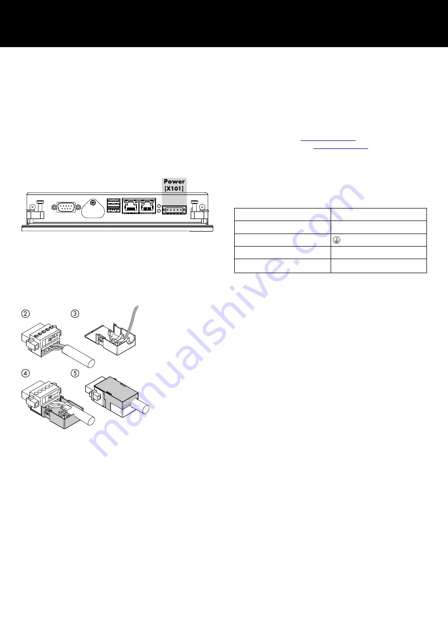
To operate the R90, an exernal 24 VDC power supply capable of

delivering a minimum of 12 W (500 mA) is required. To supply

power to the device, use the power socket 

[X101].

Pin

Signal

1 / 2

n.c.

3

4

GND

5

+ 24 V

DC

2.2  Fitting the power supply cable
Tools required :
 Flat-head screwdriver 2 x 0.4 mm.

1. Strip insulation from the cable ends (length of stripped

conductor is 8 - 9 mm).

2. Plug in the cable ends to the 5-pole plug connector in

accordance with the wiring table above.

3. Thread the cable tie into the lower part of the strain relief

housing.

4. Place the plug connector into the lower part of the strain relief

housing. Tighten the cable tie and cut off the remaining plastic

strap.

5. Fix the upper part of the strain relief housing by snapping it

onto the lower part.

Fit the power supply cable

2  R90 Hardware


d&b R90 Manual 1.6 en

5

Summary of Contents for R90

Page 1: ...R R90 Manual 1 6 en ...

Page 2: ...ebsite for the latest version of this document When reselling this product hand over this document to the new owner If you supply d b products please draw the attention of your customers to this document Enclose the relevant documents with the systems If you require additional documents for this purpose you can order them from d b d b audiotechnik GmbH Co KG Eugen Adolff Str 134 D 71522 Backnang G...

Page 3: ...supply cable 5 2 3 LAN 6 2 4 USB 6 2 5 Ground connection 6 2 5 1 Earthing measures 6 2 6 Connecting cables 6 3 R90 Software 7 3 1 Software Terms of Use 7 3 2 Interface 7 3 3 Settings 8 3 3 1 Login 8 3 3 2 System configuration 8 3 3 3 Project setup 10 3 4 System time and date 13 3 5 Factory reset 13 4 R90 Web Remote interface 14 5 R90 Log 15 Contents d b R90 Manual 1 6 en 3 ...

Page 4: ...trol software Using the OCA AES70 protocol it allows easy setup and control without the need of any additional program code Feature set Up to 15 devices Recalling up to 9 presets Global power on off Master mute Grouping Mute Level 1 3 Technical specifications Interfaces 1 x on board Ethernet adapter 10 100BASE T with RJ 45 connection 2 x USB 2 0 Protection class Front side IP54 Rear side IP20 Perm...

Page 5: ...e of delivering a minimum of 12 W 500 mA is required To supply power to the device use the power socket X101 Pin Signal 1 2 n c 3 4 GND 5 24 VDC 2 2 Fitting the power supply cable Tools required Flat head screwdriver 2 x 0 4 mm 1 Strip insulation from the cable ends length of stripped conductor is 8 9 mm 2 Plug in the cable ends to the 5 pole plug connector in accordance with the wiring table abov...

Page 6: ...he USB ports 2 5 Ground connection The device is grounded via the M4 Ground connection 2 5 1 Earthing measures Earthing connections bleed off interferences from external power supply cables signal cables or cables to peripheral equipment Establish a low resistance connection from the earthing point of the device housing Þ Ground connection to the central earthing point onsite e g the equipment cab...

Page 7: ...l For more information about the web remote control please refer to Þ Chapter 4 R90 Web Remote interface on page 14 Quick tab 1 Power Main power switch 2 Mute Master mute function 3 AmpPresets Recall presets from the devices Menu bar 4 Time and date 5 Preset switch Three presets out of a maximum of nine presets can be displayed at once The preset switch is activated as soon as a project includes m...

Page 8: ...lly Static or obtain it automatically via DHCP To set your IP address manually please proceed as follows 1 Check the Static option 2 Enter your IP address and subnet mask 3 Select Apply The device restarts automatically Firmware update A new firmware can be loaded and installed via the USB ports of the device The folder with the new unzipped firmware package must be stored in the root directory of...

Page 9: ...roceed as follows 1 Make a tick on the Screen locking option The manual locking option is now activated 2 Navigate to the home screen 3 Select the Screen unlocked button The screen is now locked no touchscreen input is possible The icon on the button changes from an unlocked to a locked padlock 4 To unlock the screen select the Screen locked button The button icon changes to an unlocked padlock Au...

Page 10: ...o bypass the lock screen proceed as follows 1 On the home screen select the Screen locked button The number pad is shown 2 Select the Admin button The normal login screen is shown 3 Enter your user name and password 4 Select Enter If the login is successful the screen is unlocked automatically 3 3 3 Project setup Device On the Device tab you can set up devices and assign the IP address to each dev...

Page 11: ...e stored in a folder on the USB drive named Preset The icon files must be in bitmap bmp or portable network png format 40 x 40px and must follow a certain naming convention Bitmap Preset 1 Preset 2 Preset n File name ON state Preset On 1 Preset On 2 Preset On n File name OFF state Preset Off 1 Preset Off 2 Preset Off n PNG Transparent background Preset 1 Preset 2 Preset n To set an individual butt...

Page 12: ...nctionalities are not available for DS100 devices Grouping On the Grouping tab device channels can be combined in a group Each group can be addressed and controlled individually using the Group control function on the home screen To assign device channels to a group please proceed as follows 1 Select a group number in the Select Group field 2 Enter a Group name 3 In the table select all channels b...

Page 13: ...e to USB The project folder is written to the root folder of your USB drive 3 4 System time and date Navigate to Home To set your local device time and date please proceed as follows 1 In the menu bar on the home screen select and hold the clock for 2 seconds The Time Date screen appears 2 Set time and date correspondingly 3 Select Apply to save your settings 3 5 Factory reset Navigate to Home To ...

Page 14: ...URL into the address line of your browser http LocalHost 2 Instead of LocalHost enter the IP address of your R90 Example http 192 168 1 90 Keyboard entries Entries may also be made using a USB keyboard However depending on the behavior of the browser or its settings some characters may not be accepted or may change the focus Therefore we recommend you to use the mouse on the onscreen input masks a...

Page 15: ... messages Or select Clear to delete all log entries irrevocably System messages Message Description No IP address No IP address has been defined in the system configuration Connection lost An already established connection to an amplifier is lost Check the cable and the power supply No connection No amplifier with the specified address has been found Connection established The connection to an amp...

Page 16: ......

Page 17: ...D2403 EN 01 02 2022 d b audiotechnik GmbH Co KG www dbaudio com ...

Reviews: