30
PRELIMINARY
1M28, 1M75, and 1M150 User’s Manual
03-32-00525-04
DALSA
Clocking Signal
Indicates
FVAL (high)
Outputting valid frame
LVAL (high)
Outputting valid line
DVAL (high)
Valid data
STROBE (rising edge)
Valid data
Digital Data
The 1M28 digitizes internally to 10 bits and outputs either all 10 bits or the most significant 8 bits
on the Camera Link connector. The 1M75 and 1M150 only output the most significant 8 bits.
2.9 Timing
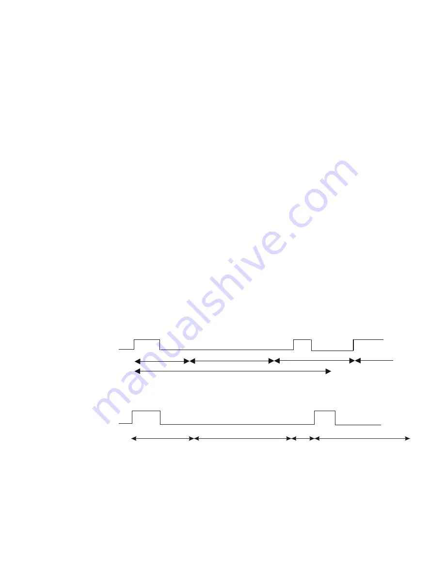
The cameras feature many possibilities for flexible timing. In free running mode, the camera
delivers, independently of external signals, data according to the timing settings in the internal
registers. In triggered mode, the camera starts integration after an external trigger pulse. During
integration and readout all further trigger pulses are ignored. The maximum rate at which the
camera accepts external triggers is defined by the frame timer. The minimum exposure time, for
any operating mode, is 560 ns.
Frame Timer
The frame timer is used to fix the frame rate of the camera in free running mode or to set the
maximum rate at which the camera accepts external triggers. In order to obtain the maximum
frame rate, the frame timer must be set as close to the sum of the readout time, exposure time, and
reset time as possible. This is especially important if the frame rate is to be increased by
windowing.
Note:
The reset time is small, at 1-2µs.
Figure 19: External Trigger Mode, Constant Image Data Rate
Integration
Readout
Frame Timer
Exsync
Ignored
Exsync
Integration
Reset
Figure 20: External Trigger Mode, Variable Image Data Rate
Integration
Readout
Reset
Integration


