www.dalemans.com
DAT420_MAN02_EN.docx • V1R1
7
DAT 420
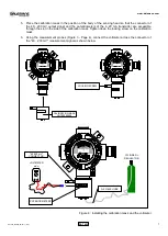
5. Place the calibration mask in the position of the body of the sensing head so that the connector of
the 40…200 mV output signal and the potentiometers of the 4..20 mA transmitter are accessible
through the slot in the side of the calibration mask. Tighten down the locking screw on the calibration
mask.
6. Using the measurement probes (Figure 3 - Page 4), connect the voltmeter across the connector of
the "40…200 mV" measurement signal as shown below.
Figure 6 : Installing the calibration mask and the voltmeter
CY
REGULATOR
VOLTMETER
mV
═
+
-
+
-
LOCKING SCREW
CALIBRATION MASK
OUT00000089
"40..200 mV"
CONNECTOR
POTENTIOMETERS
FLEXIBLE HOSE


