DALBO CULTITRAIL 500 Manual Download Page 30


CULTITRAIL 


Page 30 

Replacement andrepairs 


Safety is vital for all repair work. Always observe the following points, plus those 
under Safety First in the instruction manual. 


All maintenance and repair work can only be performed when the machine is low-
ered  to  the  ground,  the  tractor  is  braked,  engine  stopped  and  ignition  key  re-
moved to prevent accidental start. 


Particular attention must be paid to safety when repairing hydraulics. Depressu-
rise the hydraulic system before starting work.  


When replacing cylinders, always fill new cylinder with oil before pressurising sys-
tem.  We  recommend  fitting  cylinder to  frame  first, fill  with  oil, before  completing 
fitting at top. 


Hydrauliccylinders 


Hydraulic cylinder replacement 


The machine must be fully extended and standing on ground for repairs. If a wheel 
cylinder is to be replaced for example, bring the wheels to a position in which the 
wheel rests on the ground. Depressurise the cylinder by putting the tractor's hy-
draulic handle in the flow position. 


1.


Depressurise  cylinders.  Discon-
nect hoses.  

2.


Remove split pins and pins. Cylin-
der will now be free. 
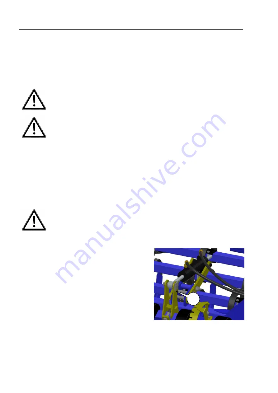
3.


Fit new or repaired cylinder. Check 
pin locks into the pin stop (A), se-
cure pins with split pins. 

4.


Connect  hoses.  Check  there  is  no 
danger  of  hoses  being  ripped  or 
crimped after fitting. 


Summary of Contents for CULTITRAIL 500

Page 1: ...CULTITRAIL EN 500 600 cm Serial no 00100 XXXX ...

Page 2: ......

Page 3: ... and serial number A spare parts list is included at the back of this manual EU DECLARATION OF COMPLIANCE DALBO A S DK 7183 Randbøl declares herewith that the above machine is manufactured in accordance with the provisions of directive 2006 42 EC which replaced directive 98 37 EC and change directives 91 368 ECC 93 44 ECC and 93 68 ECC on harmonisation of member state legislation concerning health...

Page 4: ...ONSTRUCTION 12 Construction with pin stop 13 Hydraulics to raise fold side sections 13 Hydraulics for levelling board and wheel frame 14 Bleeding the system 14 CONNECTING AND DISCONNECTING 15 CONNECTING 15 Hydraulichoses 15 DISCONNECTION 16 SETTING UP 17 BASIC SETTING 17 Working depth 17 Side pull 18 Wheel scrapers 19 Adjusting crackerboard 19 OPERATION 20 EXTENDING AND RETRACTING 20 Extension 20 ...

Page 5: ...E 27 LUBRICATION 27 Hydraulic cylinder maintenance 27 Removal fitting wheel 29 Adjustment and lubrication of wheel bearings 29 Hydraulics 29 Tips 29 REPLACEMENT ANDREPAIRS 30 HYDRAULICCYLINDERS 30 Hydraulic cylinder replacement 30 Bleeding 31 REPLACING WHEEL BEARINGS 31 Assembly 31 REPLACING TIPS 32 Crackerboard 32 SCRAPPING 33 GUARANTEE 34 HYDRAULIC DIAGRAM 35 SPARE PARTS 36 ...

Page 6: ...rforming maintenance or repairs on the machine fully lower machine to the ground apply tractor hand brake switch engine off and remove ignition key to prevent accidental opera tion Remember to secure top arm and lift arm if relevant with split rings Never leave driver s seat whilst machine is moving Always adapt speed to conditions Do not use machine unless all safety devices are in place Defectiv...

Page 7: ...r and maintenance work Ensure tractor and machine are properly braked engine stopped and ignition key removed Tighten all screw connections after a few hours use Check all screw connec tions regularly and tighten as required Check all split pins and bolts to avoid mechanical failure Dispose of oil grease and filters in accordance with local environmental pro tection rules Road transport All safety...

Page 8: ...r repaired by personnel familiar with it and who are aware of the risks that can be involved The manufacturer cannot be held liable for injury or damage arising from modi fications made to the machine performed without prior permission from the manufacturer Neither can the manufacturer be held liable for injury or damage arising from incorrect use Such liability rests solely with the user Do not a...

Page 9: ...weight kg 2300 2500 Transport width 2 5m 2 5m Transport height 2 9m 3 4m Wheels 300 55 14 5 4 4 Tines no 63 77 Delivery The machine is delivered complete on a trailer The machine can be partially dis mantled if exported If lifting the machine we recommend the use of straps on the mid section to main tain balance ...

Page 10: ...to the table of contents for page numbers for individual items The manual is divided into main sections Safety Description including settings Starting routine and running Accessories Maintenance Repairs The following symbols represent Points which are important to functionality and service life Points relevant to safety ...

Page 11: ...ormal agricultural maintenance i e with no significant unevenness or holes The machine can only be used towed behind an agricultural tractor and must be connected to the tow bar Maximum working speed is 15 kph But always adapt speed to the nature of the area to be worked Use of the machine which does not fulfil the conditions above will be regarded as non authorised and will invalidate the factory...

Page 12: ...vy duty crackerboard at the front to level the soil and crush clods The crackerboard depth is hydraulically adjustable from the tractor cab Harrow depth is controlled by the 4 large wheels which are steered by a hydraulic sys tem to ensure the same depth is always maintained A simple mechanical stop mecha nism on the 2 centre wheel cylinders provides depth regulation without the use of tools The h...

Page 13: ...ders A and B are linked to the same hose via a T piece Folding out requires min pressure in cyl B Lock C is therefore lifted free of pin D before the side section is pressed out wards downwards Throttle nipple E controls lowering speed of the side sections when they pass the point of gravity Cyl B has an internal spring which retracts it as soon as the hose is de pressurised The lock automatically...

Page 14: ... fully retracted even if using the tractor s over pressure valve The system will now be bled The hydraulic cylinders for the front levelling board are linked in the same way Use the same proce dure for bleeding Fig 4 The hydraulic cylinders A are linked in series with the cor responding wheel frame cylinder on the side section When the wheel frame is raised the tractor pumps oil to B the centre cy...

Page 15: ... the tow bar Remember to secure the support leg split pin C 4 Fit hydraulic hoses and open ball cock for flow to wheel frame Hydraulichoses A double action outlet is required to connect CULTITRAIL Hose markings Function Colour Wheel frame ball cock White Extension retraction of side sections Red Crackerboard Green Check hydraulic hoses for crimping Close ball cock for wheel frame when transporting...

Page 16: ...all cock Remember to depressurise hoses before disconnecting them If connecting machine in transport position check transport safety device A is engaged Place the machine on a firm flat surface Fit support leg B on draw bar and lower until draw bar is lifted free of the tow bar The machine can now be disconnected A B ...

Page 17: ...nt end of the harrow frame Remember to tighten the re verse thread wing nut B when adjustment is complete If the harrow is raised the weight on the top bar will be very heavy Lower before adjusting top bar Adjustment can be made easier by pressing the front cracker board hard into the soil using the tractor hydraulic system Working depth Fig 8 Adjust working depth using the hose length limiters fi...

Page 18: ...ts on the side sections to adjust Adjustment procedure Example if the machine is pulling to the right lower the wheel cylinder bracket on the right side section a little This will raise the entire side section a little counteracting side pull The setting only needs to be made once and only if side pull is occurring The setting option is standard on machines with serial numbers higher than 00127 Ne...

Page 19: ...djusting crackerboard Fig 11 The foremost implement the cracker board is fully hydraulically adjustable from the tractor Depth is shown on the indicator A which is visible from the driver s seat The crackerboard hy draulic system is fitted with a throttle to ensure smooth even movement regardless of the amount of oil coming from the tractor The board is not intended to work as a dozer blade to avo...

Page 20: ...ty reasons and to ensure the transportation locks engage Before the machine can be extended or retracted the tractor driver must ensure there are no personnel near the machine Otherwise there can be a risk of injury Extension Fig 12 Activating the hydraulic handle red for extension and retraction releases the automatic transportation lock and the side sections will extend When the side sections ar...

Page 21: ...enting accidental operation Operating speed To achieve optimum cultivation a speed of between 8 and 12 km h is required But always work according to the conditions Please note that wear increases significantly in line with the speed The tines can also be damaged if operating at excessive speeds in unfavourable conditions Wear will increase significantly at high speeds particularly under dry condit...

Page 22: ... adjusted on the post harrower Depending on working depth A can be moved to B The post harrower will then work deeper Aggressiveness can be reduced by moving C to D Finally spring tension can be adjusted using the nuts E This adjusts how much of the harrow weight is transferred to the post harrower Fig 14 The post harrower working depth cannot be adjusted such that the suspension arms G are consta...

Page 23: ... these holes the spindles A must be shortened to avoid the board exerting too much pressure on the ground Fig 15 The purpose of the board is to level the soil surface after the harrow tines and to crush press down clods If the board is forced downwards too hard or works at an angle which is too flat if using holes B clods could roll over the board and be left on the soil surface We therefore do no...

Page 24: ... mount the arms in D The mounting holes E in the suspension arms can be used to mount the packing roll ers but only if the machine is not mounted with a rear levelling board Otherwise there is not enough room for the board to avoid stones The weight transferred by the packing rollers from harrow to ground can be adjusted using the nuts H If the springs are tightened more weight is transferred to t...

Page 25: ...o mount the arms in D The mounting holes E in the suspension arms can be used to mount the rollers but only if the machine is not mounted with a rear levelling board Otherwise there is not enough room for the board to avoid stones The weight transferred by the rollers from har row to ground can be adjusted using the nuts H If the springs are tightened more weight is transferred to the rollers Fig ...

Page 26: ... mount the arms in D The mounting holes E in the suspension arms can be used to mount the roll ers but only if the machine is not mounted with a rear levelling board Otherwise there is not enough room for the board to avoid stones The weight transferred by the rollers from harrow to ground can be adjusted using the nuts H If the springs are tightened more weight is transferred to the rollers Fig 1...

Page 27: ...opped and ignition key re moved to prevent accidental start and crushing Lubrication Hydraulic cylinder maintenance All hydraulic cylinders are high quality and fulfil anti corrosion requirements Nevertheless long periods of inactivity can mean a risk of rust attack on exposed ram shafts In such instances new cylinders will have to be fitted It is therefore important to apply grease or thick oil t...

Page 28: ...ges 50 2 B Wheel frame bracket on main frame 50 2 C Wheel frame bracket on side section 50 2 D Top bar eye bottom 20 1 E Cylinder for retraction 50 2 F Bearings in Flat iron or tubular roller op tional extra 50 6 G Bearings in Crosskill roller optional extra 50 14 G Lubricate all lubrication points at least once annually A B A C D E F F G ...

Page 29: ...ts and wheel surfaces are clean to avoid nuts loosening Adjustment and lubrication of wheel bearings 1 Remove wheel 2 Remove hub caps 3 Remove split pin 4 Tighten castle nut 1 6th of a turn until hole aligns with axle Hub housing should be able to rotate freely with no play when moved from side to side If play is excessive repeat process 5 Replace split pin 6 Fill hub cap full with grease Replace ...

Page 30: ... oil before pressurising sys tem We recommend fitting cylinder to frame first fill with oil before completing fitting at top Hydrauliccylinders Hydraulic cylinder replacement The machine must be fully extended and standing on ground for repairs If a wheel cylinder is to be replaced for example bring the wheels to a position in which the wheel rests on the ground Depressurise the cylinder by puttin...

Page 31: ...re no personnel are within the extension radius of the side sections Replacing wheel bearings Fig 20 1 Remove hub cap pos 21 2 Remove split pin pos 20 3 Remove castle nut pos 19 4 Remove hub cap pos 22 5 Remove bearings pos 17 18 6 Remove seal ring pos 16 Assembly 1 Fit bearing outer rings pos 17 18 in hub housing pos 22 2 Fit seal ring pos 16 3 Fit bearing inner ring pos 18 on axle pos 2 and fit ...

Page 32: ...tips from the ground Fig 21 The tips A are reversible and bolted on Reverse or replace tips if the tine is worn When turning tips old bolts can be reused but when replacing them use new bolts Remove any accumulated soil between tine and tip Crackerboard Fig 22 Reverse or replace tips if before the tine becomes worn The tips can be moved down to hole A if necessary A A ...

Page 33: ...y given part when removing or disassembling All parts must be supported or lifted to avoid danger of falling Disconnect hydraulic hoses and cylinders and drain oil Collect oil in container to avoid pollution Send oil and hoses for destruction All iron used in the machine can be recycled ...

Page 34: ...e without the written consent of DALBO A S Non original spare parts used DALBO A S cannot be held liable for consequential damage loss of earnings or production as a result of defects DALBO A S cannot be held liable for the cost of labour apart from that reasonably incurred for repair or replacement covered by the guarantee DALBO A S cannot be held liable for the following costs Setting the machin...

Page 35: ...ve ventil Lamelplanke Crackerboard Grøn Green 91792 25 60 25 X 205 91792 25 60 25 X 205 91792 25 60 25 X 205 91808 80 40 X 700 Ø25x75 91792 25 60 25 X 205 91792 25 60 25 X 205 91792 25 60 25 X 205 91792 25 60 25 X 205 1 5 mm 91135 1 5 mm 91135 Kugle spærreventil 50573 44310 70 30 X 205 Ekstra løftecylinder på Cultitrail 6m med valser i bag Additional cylinder on Cultitrail 6m with rear rollers ...

Page 36: ...CULTITRAIL Page 36 Spare parts ...

Reviews: