background image

– 14 –

•  To enter a new line of text, press the 

Enter

 key.

•  To insert a new page to the message, type or press

 Enter

 through 3 lines of text and 

then press 

Enter

 to create a fourth line. The fourth line adds a page. 

•  To delete a character, press the 

left arrow

 key.

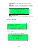
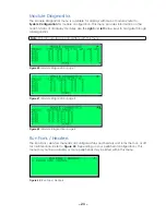
After completing the message, press 

Cancel

. The Save Message menu opens; refer to 

Figure 16

.

1. 

Save in X 

saves in the first open slot.

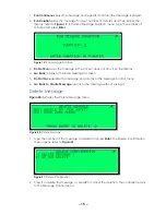
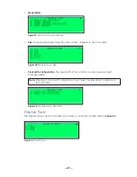
2. 

Save in Another Slot 

opens the Save Message As menu; refer to 

Figure 17

. Enter the 

slot number to save the message in and press 

Enter 

to save. 

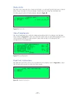
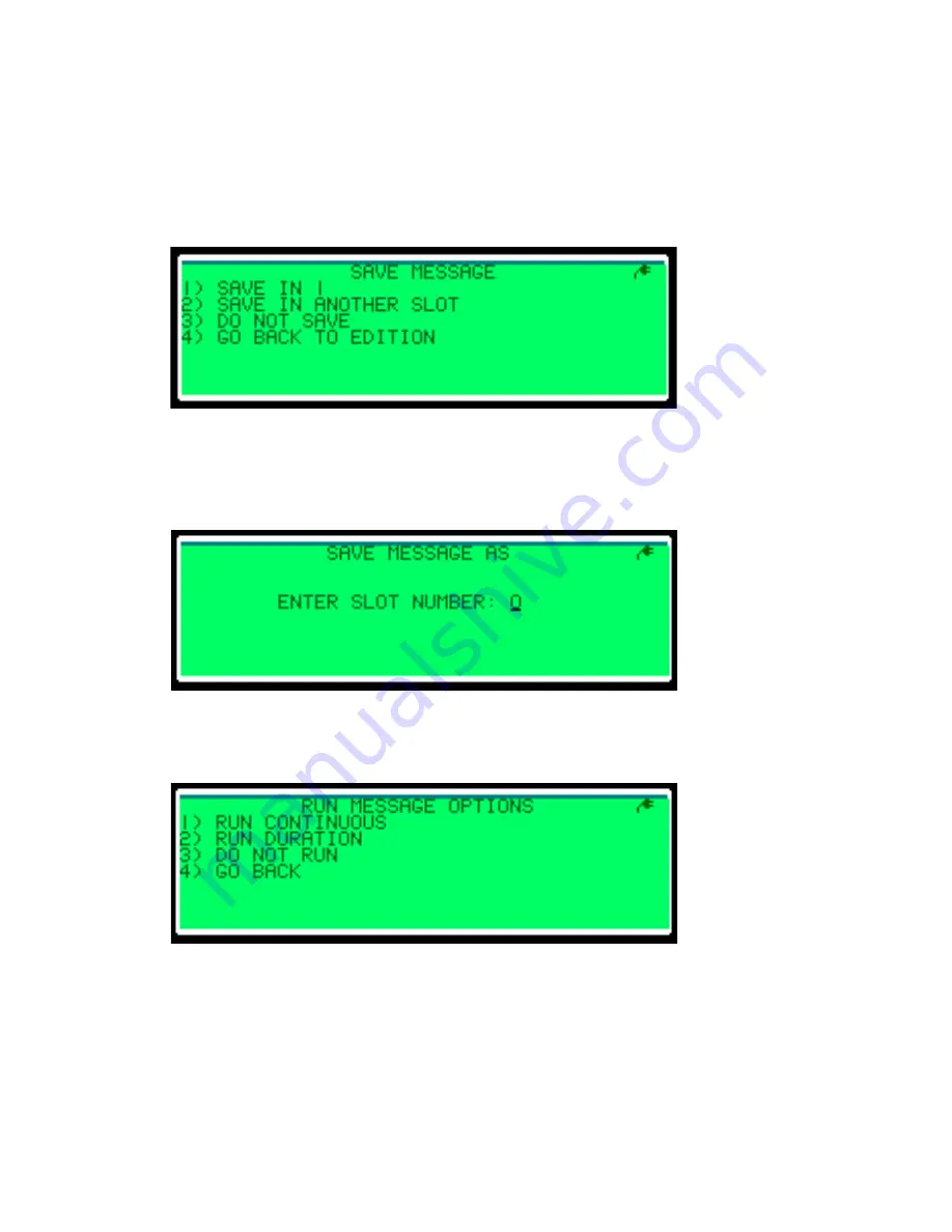
The Run Message Options menu opens; refer to 

Figure 18

.

Figure 16: 

Save Message

Figure 17: 

Save Message As

Figure 18: 

Run Message Options

Summary of Contents for VFC-3000

Page 1: ...201 Daktronics Drive Brookings SD 57006 5128 www daktronics com support 800 325 8766 GENERIC SERVICE VFC 3000 CONTROLLER OPERATION MANUAL 25 May 2018 DD3929569 Rev 0...

Page 2: ...art of this book covered by the copyrights hereon may be reproduced or copied in any form or by any means graphic electronic or mechanical including photocopying taping or information storage and retr...

Page 3: ...Message 13 Delete Message 15 Quick Schedule 16 6 Diagnostics Menu 17 Version Info 18 Status Info 19 View Peripherals 19 Pixel Test Activation 19 Pixel Test Results 20 Pixel Test Results Bitmap 20 Pixe...

Page 4: ...m Errors Menu 42 11 Change Password Menu 43 12 Maintenance and Troubleshooting 44 Getting Started 44 Required Tools 44 Replacement 44 Maintenance 44 Troubleshooting 45 13 Daktronics Exchange and Repai...

Page 5: ...ver page of each manual For example this manual is referred to as DD3929569 Theory of Operation The Daktronics VFC 3000 controller is the communication hub for DMS management it is located in the disp...

Page 6: ...Mini CAN I O Board Door 1 Sensor Opt Traffic Cabinet Dynamic Message Sign CAN Distribution Board DC I O Board Door Sensors Fan Sensors Front Light Sensor Rear Light Sensor Bottom Light Sensor Externa...

Page 7: ...e Switch Power Switch The Power switch in the lower left corner of the front panel interface turns the controller s power on and off The Power LED on the right side of the interface indicates that the...

Page 8: ...ode during an emergency LCD Screen The LCD screen displays status information display information and menus It also displays informational icons Figure 3 explains these icons To adjust LCD contrast en...

Page 9: ...romagnetic interference It enables the VFC 3000 controller to be located up to 2 500 762 m from the display The fiber optic option requires a pair of 62 5 125 m fibers with ST connectors Connect the t...

Page 10: ...display is correct Refer to the software controller operation manual for configuring the display database The communication cables and devices are operational The communications software parameters a...

Page 11: ...PP no handshaking at 9 600 bps Refer to Communication Configuration to configure this port To use the internal modem connect the incoming telephone line from the telephone company to J6 using an RJ11...

Page 12: ...ort on the VFC 3000 controller is labeled as Local Sensor J2 on the rear of the controller A CAN network port is provided on the CAN distribution board inside the display The DC I O board has several...

Page 13: ...igure 5 shows the display legibility Line 7 shows the current mode remote While in remote mode press the up and down arrow keys to adjust LCD contrast Local Mode Logging In Users must log into the VFC...

Page 14: ...ts dimming type and dimming level Refer to Brightness Control Menu 4 Configuration Sets up system communication and peripheral options Refer to Configuration Menu 5 Current Display Shows what is curre...

Page 15: ...e Run Saved Message menu lets you choose a saved message and play it on the display Messages are listed in alphabetical order Refer to Figure 9 1 Type the number of the message to preview and press En...

Page 16: ...the message and returns to the Message Control menu Go Back returns to the Run Saved Message menu Preview a Message The Preview a Message menu illustrated in Figure 12 lets you view a message on the...

Page 17: ...pages and each page can have 3 lines of text To enter a character press the number key associated with the number or letter you wish to type Press the number key repeatedly until the desired characte...

Page 18: ...ress the left arrow key After completing the message press Cancel The Save Message menu opens refer to Figure 16 1 Save in X saves in the first open slot 2 Save in Another Slot opens the Save Message...

Page 19: ...k returns to the Save Message As menu 5 Do Not Save deletes the message and returns to the Message Control menu 6 Go Back to Create Message returns to the message without saving it Delete Message Figu...

Page 20: ...d with the central controller To play the quick schedule 1 Press 1 to start the schedule refer to Figure 23 2 Press 1 to confirm the start of the schedule or press 2 to cancel After starting the sched...

Page 21: ...ates the first page of the Test Patterns menu Press the up and down arrow keys to navigate through all options in the Test Patterns menu To run a test pattern press the number of the pattern to run Th...

Page 22: ...n Info menu lists known hardware and software versions of the components within the display Figure 27 shows the first page of the Version Info menu Use the up and down arrow keys to navigate through t...

Page 23: ...configured peripherals for the display and lists their status Refer to Figure 29 To find out more information about a specific peripheral such as the revision number and the location press the number...

Page 24: ...e progress screen When the pixel test completes the Pixel Test Results menu opens Refer to Pixel Test Results for information about this menu Pixel Test Results The Pixel Test Results menu is illustra...

Page 25: ...Pixel Test Results menu deletes all information from the last pixel test refer to Figure 35 Press 1 to delete all pixel results or press 2 to cancel the deletion Real Time Pixel Results When real tim...

Page 26: ...the pixel is stuck on or off Figure 38 illustrates a real time pixel results list with no errors a real time pixel results list with errors looks similar to Figure 35 If necessary press the up and dow...

Page 27: ...rough all diagnostics Note Not all modules are compatible with this menu Run Fans Heaters The Run Fans Heaters menu lists all configured fans and heaters and turns them on or off for maintenance Refer...

Page 28: ...urns to the Diagnostics menu To turn off the fans or to return to normal operation 1 Open the Run Fans Heaters menu 2 Press 1 to restore normal operation or press 2 to turn off the fans refer to Figur...

Page 29: ...al dimming Press the up arrow key to move between the automatic Figure 47 and manual Figure 48 dimming menus To change the dimming level percentage in the Manual Dimming menu type the percentage and p...

Page 30: ...date and time settings and serial numbers Refer to Figure 50 Configure Display The Configure Display menu enables configuration items such as display type height width and access to be set Refer to Fi...

Page 31: ...center measurement between pixels Note Entering an incorrect module type may cause module errors to appear on the controller Display Type The Display Type may be full matrix line matrix or character...

Page 32: ...ls The pixel height is restricted by the module type Because the module type selected in the Module Type menu was 9 x 5 Figure 58 requires that the pixel height must measure at least 9 pixels tall and...

Page 33: ...o any value between 1 and 255 Address 63 is reserved by NTCIP standard as a group address Configure Options Real Time Pixel Errors Real Time Pixel Errors illustrated in Figure 62 is an enhanced pixel...

Page 34: ...ls the maximum percentage of pixel errors a display can have before it does not display a message This feature prevents motorists from being distracted while reading a message that is not legible To s...

Page 35: ...ables trap settings When a trap is enabled that option is reported to the central controller To change a trap press the number of the setting to change The option toggles to the opposite setting For e...

Page 36: ...with the keypad typing a 2 for a m or a 7 for p m Then press Enter to set the time and date or press Cancel to return to DST Controller Serial Number Each VFC 3000 controller has a serial number locat...

Page 37: ...es configuration items such as communication protocol baud rate and handshaking to be set Refer to Figure 75 Central Control Port The Central Control Port menu controls settings for the controller s s...

Page 38: ...Rate to Auto but if communications are failing it may be set to Full or Half Duplex and 10 Mbps or 100 Mbps Standard Protocol is TCP IP and UDP IP but the controller can use a port server with a seri...

Page 39: ...strated in Figure 81 and Figure 82 lists peripherals supported by the controller Note The peripherals listed in the menu may vary depending on what peripherals have already been configured For example...

Page 40: ...To add a DC I O board 1 In the Add Peripherals menu press 4 The menu pictured in Figure 83 opens 2 Select the appropriate DC I O Refer to the display s Schematic and the Sign Peripheral Configuration...

Page 41: ...ing To add a ventilation fan 1 Press 5 Add Fans in the Add Peripherals menu The menu pictured in Figure 86 opens 2 To add intake fans press 1 3 Select to which target the fans attach refer to Figure 8...

Page 42: ...ipheral errors return to the Peripherals Configuration menu A new menu called Peripheral Init Errors appears at the bottom of the Peripheral Configuration menu Refer to Figure 90 To fix the errors del...

Page 43: ...tect menu Refer to Figure 93 2 Press 1 to confirm the deletion and start the auto detection procedure When this procedure completes you can view the peripherals by pressing 4 on the keypad from the Di...

Page 44: ...ntroller and removes all messages from the controller but does not restore factory defaults 4 Restore Factory Defaults resets the controller removes all messages and restores all settings back to fact...

Page 45: ...Current Display menu illustrated in Figure 96 and Figure 97 shows what is currently playing on the display To change display content refer to Message Control Menu Figure 96 Current Display frame 1 Fig...

Page 46: ...8 The System Errors menu lists any errors refer to Figure 99 To view more information about a specific error press the number next to the error For example Figure 100 provides more information about t...

Page 47: ...on mark To enter the next number or letter press the number key for that character Note If the next number or letter requires you to press the number key used for the previous character press the righ...

Page 48: ...n the VFC 3000 controller face 2 Label and remove all connections from the front and rear of the VFC 3000 controller 3 Remove the screws securing the VFC 3000 controller to the inside of the display o...

Page 49: ...se The internal power supply failed or other internal hardware malfunctioned Replace the VFC 3000 controller The display will not display test patterns or messages The display data J11 J12 or fiber di...

Page 50: ...rt J1 The Local Remote switch must be set to Remote Bad serial port or other circuitry Replace the VFC 3000 controller The RS232 surge suppressor failed Replace the VFC 3000 controller Bad modem Repla...

Page 51: ...oller cannot communicate with any displays Central software is not running Run the software Central software network settings are incorrect Ensure the network settings in the software are correct Powe...

Page 52: ...VFC 3000 software is corrupted Reset the VFC 3000 controller Then download new firmware to the VFC 3000 controller The processor board in the VFC 3000 controller is bad Replace the VFC 3000 controller...

Page 53: ...irports parking facilities 800 833 3157 2 When the new exchange part is received mail the old part to Daktronics If the replacement part fixes the problem send in the problem part which is being repla...

Page 54: ...or by creating a MySupport account on the Daktronics website This expedites repair of the part 3 Package and pad the item carefully to prevent damage during shipment Electronic components such as prin...

Page 55: ...0 controller to power the pixels The driver also controls the pixels dimming level based on data received from the VFC 3000 controller Circuitry on the driver board can test the operational status of...

Reviews: