


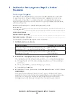


Troubleshooting
20
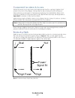
To replace a digit:
1�
Open the digit panel as described in
Component Locations & Access (p�19)
2�
Disconnect the 9-pin plug from the back of the digit by squeezing the locking tabs
together and pulling the connector free.
3�
Use a 9/32" nut driver to remove the nuts securing the digits to the inside of the panel,
and then lift the digit off the stud inserts.
4�
Position a new digit over the studs, and then tighten the nuts.
5�
Reconnect the 9-pin plug. This is a keyed connector and it will attach in one way
only. Do not force the connection.
6�
Secure the digit panel to the display face with the screws, and then power up and
test the display to verify the issue has been resolved.
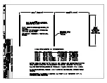
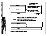
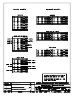
Segmentation & Digit Designation
Reference Drawings:
Segmentation, 7 Segment Bar Digit ...................................................................
DWG-38532
In each digit, certain LEDs always go on and off together. These groupings of LEDs are
referred to as segments.
DWG-38532
in
Appendix B
details which connector pin is wired
to each digit segment and the wiring color code used throughout the display.
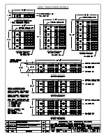
The Electrical Specification drawings in
Appendix B
also specify the driver connectors
controlling the digits. Numbers shown in the upper half of each digit indicate which
connector is wired to that digit.
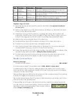
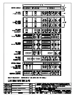
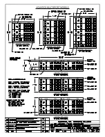
LED Drivers
LED drivers perform the task of switching digits on and off within the display. LED drivers
are mounted to a driver tray inside a protective enclosure. Refer to
to view the
location and components of a driver tray.
H
L
0
1
2 3 4 5 6
7
8
9
A
B
C
D
E
F
0
1
2 3 4 5 6
7
8
9
A
B
C
D
E
F
1
SIGNAL
5
TAN
4
PNK
3
VIO
2
BLK
RED
TRANSFORMER
3
2
1
4
5
10
9
7
6
TAN
PNK
BRN
ORG
BLU WHT
8
8
WHT
BLU
ORG
BRN
PNK
TAN
6
7
9
10
5
4
1
2
3
TRANSFORMER
CUR. LOOP
PT
SIGNAL IN
SIGNAL OUT
HAZARDOUS VOLTAGE
AT EXPOSED TERMINALS.
DISCONNECT POWER
BEFORE SERVICING.
TENSION DANGEREUSE
À
TERMINAUX EXPOSÉS
DÉBRANCHEZ L'ÉLECTRICITÉ
AVANT L'ENTRETIEN.
RED BLK
2
VIO
3
PNK
4
TAN
5
SIGNAL
1
3
2
1
4
5
10
9
8
7
6
TAN
PNK
BRN
GRY
ORG
BLU WHT
TRANSFORMER
HAZARDOUS VOLTAGE
AT EXPOSED TERMINALS.
DISCONNECT POWER
BEFORE SERVICING.
TENSION DANGEREUSE
À TERMINAUX EXPOSÉS
DÉBRANCHEZ L'ÉLECTRICITÉ
AVANT L'ENTRETIEN.
Driver Status
Indicators
Driver Status
Indicators
16-Column
LED Driver
16-Column
LED Driver II
Signal Terminal Block
Signal Terminal Block
Signal Terminal Block
Transformers
Transformers
Transformer
LED Driver Tray (Gyrus)
LED Driver Tray
(prior to April 2015)
MASC LED Driver Tray
(TI-2200 Only)
4-Column LED Driver II
Driver Status
Indicators
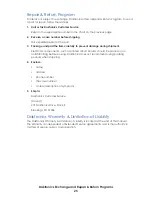
Figure 10:
Driver Tray Components (Enclosure Cover Removed)
When troubleshooting driver problems, several LEDs provide diagnostic information.
Note:
While it is necessary to have the display powered on to check the LED status
indicators, always disconnect power before servicing.
Summary of Contents for SW-2001
Page 30: ...This page intentionally left blank ...
Page 32: ...This page intentionally left blank ...
Page 33: ......
Page 34: ......
Page 35: ......
Page 36: ......
Page 37: ......
Page 38: ......
Page 39: ......
Page 40: ......
Page 41: ......
Page 42: ......
Page 43: ......
Page 44: ......
Page 45: ......
Page 46: ......
Page 47: ......
Page 48: ......
Page 49: ......
Page 50: ......
Page 51: ......
Page 52: ......
Page 53: ......
Page 54: ...This page intentionally left blank ...
Page 56: ...This page intentionally left blank ...
Page 57: ......
Page 58: ......
Page 60: ......
Page 61: ......
Page 63: ......
Page 64: ......
Page 65: ......
Page 66: ......
Page 67: ......
Page 68: ......
Page 69: ......
Page 74: ......
Page 75: ......
Page 77: ......
Page 82: ...This page intentionally left blank ...


