Display Installation
5
8�
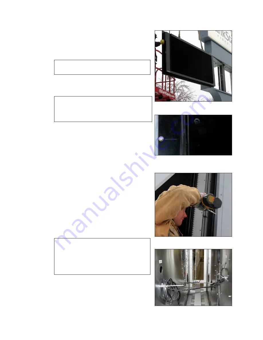
Using a boom or other lift equipment, position the Daktronics primary display beside
the sign structure. Lift the display from above
with the lift eyes.
9�
Partially slide the Galaxy
®
eCCB display into
place within the remaining perimeter retainers
Note:
Do not rest the display on the bottom
retainers.
10�
Leave enough room between the Daktronics
display and the front of the changeable copy
board to make all electrical connections.
Note:
In 2V display installations, when there
is no access to the signal cable, make
the connection through the access
panel on the mirror face.
11�
Center and level the display, so the flanges
are evenly spaced on all sides in the structure.
12�
Insert a self-tapping screw through the display
flange, and the structure at each of the
etched locations on the Galaxy
®
eCCB display
flanges. Refer to
. Screws are provided
and are located in the installation kit.
13�
Re-install the perimeter retainers overlapping
the flanges on the Galaxy
®
eCCB display.
14�
In the case of a 2V display; repeat steps 7
through 11 for the second face. Make the
signal connection between the primary and
mirror face using the already installed signal
cables before the second face is fully
mounted. Refer to
.
15�
Repair and seal any unused openings in the
existing changeable copy board display
structure.
Note:
Openings greater than
1
/
2
″ (12.7 mm)
in diameter require a metal patch
secured by screws or rivets and
caulked with non-hardening caulk.
Smaller openings may be sealed with
non-hardening caulk.
16�
Start up the display and verify it is working
properly using a cellular phone or tablet
computer with Wi-Fi.
Figure 3:
Slide eCCB Display into Place
Figure 4:
Attachment Point with
Embossed Marking
Figure 5:
Reattach Copy Board Retainers
Figure 6:
Primary to Mirror Signal Cable
Connection


