background image

Section 7: 

RC-50 Controller 

The RC-50 controller can be configured to program petroleum price variances displayed on the LED 
DataMaster Petroleum Price sign. The instructions provided in this section discuss the functions used 
by the operator to control the Petroleum Price display. 
 

Reference Drawing:


RC-50 Quick install Guide ............................................................................... 

Drawing A-257189


7.1  RC-50 Operation 

The RC-50 controller can control four unique prices on multiple signs. The instructions 
provided in this section discuss the functions used by the operator to control the rate display.  

Editing the Display 

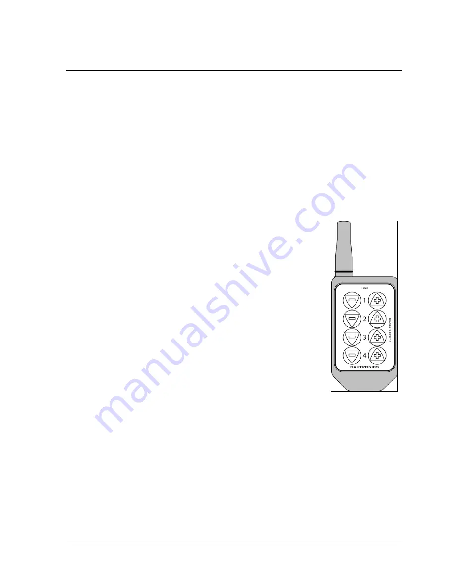
To edit the price on the display, press and hold any button for five 
seconds. When the sign is in Edit mode, the decimal LEDs blink. 


Figure 26: RC-50 

Controller 


On the RC-50, each pair of buttons corresponds to a price line on the 
display. Each line is numbered to indicate the corresponding line on 
the display.  

Increasing the price 

To increase the price by one cent, press 

[+]

 for the corresponding line. 

Note: 

Make sure the display is in Edit mode. 

Decreasing the price 

To decrease the price, press

 [-]

 for the corresponding line. 

Note: 

Make sure the display is in Edit mode. 

Turbo mode 

To rapidly increase or decrease a price, press and hold the button for 
the corresponding line. 


Note:

 When a button is not pressed for more than 10 seconds, the 

display exits the Edit Mode. The prices are saved and the 
display returns to its normal state. 


RC-50 Controller 


33 


Summary of Contents for DF-2009 Series

Page 1: ...9 Series 36 48 and 60 digits Installation and Operation Manual ED 18514 Rev 0 2 July 2007 201 Daktronics Dr PO Box 5128 Brookings SD 57006 Tel 866 343 3122 605 697 4300 Fax 605 697 4444 Hwww daktronic...

Page 2: ...nication Network address DAKTRONICS INC Copyright 2008 All rights reserved While every precaution has been taken in the preparation of this manual the publisher assumes no responsibility for errors or...

Page 3: ...over Page and Copyright Page are blank on back Section heading pages always start on the right hand page 3 Group and insert the drawings as listed in Appendix A Reference Drawings Print all A drawings...

Page 4: ......

Page 5: ...ddress Dip Switch Settings 9 3 3 Power Up Self test 9 Section 4 Diagnostics and Troubleshooting 11 4 1 Driver Location and Access 11 Driver LEDs 12 Power On Self Test 12 4 2 Troubleshooting 13 Section...

Page 6: ...ller 33 7 1 RC 50 Operation 33 Editing the Display 33 Section 8 RC 100 Controller 35 8 1 Petroleum Price Display Operation 35 Petroleum Price Display Startup 35 RC 100 Controller Operation 36 Modifyin...

Page 7: ...ation 7 Figure 11 Location of Signal Driver 8 Figure 12 Driver 9 Figure 13 Dip Switches 9 Figure 14 Location of Driver Inside Display 11 Figure 15 Driver Diagnostics 12 Figure 16 Locations of Internal...

Page 8: ......

Page 9: ...sume little power some barely more than a household lamp Figure 2 DF 2109 with Top Caption The DF 2009 and DF 2109 displays are two models of DataMaster Petroleum Price displays These models include d...

Page 10: ...drawing Figure 4 This reference number includes the last set of digits and the letter preceding them The drawing in this example would be referred to as Drawing A 244838 Figure 4 Daktronics Drawing La...

Page 11: ...ndix A The shop drawings provide the display dimensions weight location of mounting hardware and component locations Refer to the Shop Drawing for the specific display type and size when planning the...

Page 12: ...fting the Display Eyebolts may be removed once the display is in place Replace the eyebolts with 1 2 13 bolts 2 3 Mounting Displays Mechanical installation consists of mounting the display onto horizo...

Page 13: ...as illustrated in Figure 8 providing power and ground to a disconnect near the display routing power and ground from the main disconnect to the display connecting the display ground to a ground rod at...

Page 14: ...ystem must be connected to an earth electrode installed at the display Proper grounding is necessary for reliable equipment operation It also protects the equipment from damaging electrical disturbanc...

Page 15: ...display is not in use The controller should also be disconnected from power and from the signal j box when the system is not being used The same surges that may damage the display s driver can also d...

Page 16: ...is driver receives its signal directly from the controller on the Signal In connector J6 The Signal Out connector J8 is used to connect to client drivers the drivers in other displays in this network...

Page 17: ...In the example switches 1 and 4 are on Addresses allow the user to set both line number switches 1 3 and sign number switches 4 6 in as many as eight sign groups All displays with the same line number...

Page 18: ......

Page 19: ...y not work correctly Use this section to define the problems and find solutions 4 1 Driver Location and Access The driver is located as shown in Figure 14 mounted between two digit boards To access th...

Page 20: ...een Continuous light when driver has power DS2 Red Blinks when driver receives signal DS3 Amber Blinks when driver is running Power On Self Test A useful troubleshooting tool is the power on self test...

Page 21: ...address for each line of sign Section 3 2 Digit will not light Black wire to digit broken Poor contact at driver connection Driver malfunction Replace harness Clean contacts Replace driver Segment or...

Page 22: ......

Page 23: ...W 1578 Digit cable 8 ft W 1579 Gas Price Driver 4 col 0P 1192 0394 Signal Surge Card 0P 1356 0001 Power supply 24 V DC 1 KW A 1856R Segment Breakout Board 0P 1192 0397 10 Cash Credit Board Red 0P 131...

Page 24: ...n D male 0A 1196 0099 RC 50 Radio 0A 1356 0064 Receiver card 0P 1192 0355 Antenna A 2015 Transformer wall pack T 1118 RC 100 Price Display insert LL 2617 RC 100 hand held assembly 0A 1110 0046 RC 100...

Page 25: ...enter digits 2 Disconnect and label all connectors from the driver Release each connector by squeezing together the locking tabs and pulling on the plug 3 Remove the screws and nuts securing the drive...

Page 26: ...he defective segment As with smaller digits the segment circuit boards are mounted to the back of the digit panel Do not attempt to remove individual LEDs Replace a malfunctioning colon decimal or ind...

Page 27: ...in one way only Do not attempt to force the connection 6 Close and secure the digit panel and test the display Replacing a Breakout Board To replace a breakout board follow these steps 1 Open the spec...

Page 28: ...s Customer Service 866 343 3122 2 When the new exchange part is received mail the old part to Daktronics If the replacement part fixes the problem send in the problem part which is being replaced a Pa...

Page 29: ...on RMA number before shipping This expedites repair of the part 3 Package and pad the item carefully to prevent damage during shipment Electronic components such as printed circuit boards should be pl...

Page 30: ......

Page 31: ...aster DM 100 The DM 100 can be configured to display petroleum price motel rates and time and temperature data Refer to Drawing B 256001 for information on possible control options and connection proc...

Page 32: ...where required This control option does not require the controller to be connected to a power outlet In this configuration the DM 100 uses the sign as a power source To operate the display using this...

Page 33: ...ide it into the DM 100 pocket Use this as a reference until a replacement is received To start the controller and use the insert to program information into the display driver read the next section ca...

Page 34: ...the bottom line of the LCD during startup do nothing The controller will automatically default to previous Gas Price settings If a function other than GAS PRICE was shown on the bottom line of the LC...

Page 35: ...g the Edit key during operation or by using the Menu key refer to Menu Items chart following this screen The following keys identify items to be edited L Current line number to be edited D CC Current...

Page 36: ...play For further details refer to Modifying Price Line Settings discussed previously in this section For more information about the Modem Settings submenu refer to ED 13953 DataMaster Modem Installati...

Page 37: ...d to the DM 100 The LCD will scroll through the status sent back from the display Following is a list of responses Firmware Version This is the firmware version programmed on the host MASC driver in t...

Page 38: ...Enter key when finished editing Press the Clear key to cancel changes After setting the time you will need to set the date If the date is already correct enter through the date and press Enter to sen...

Page 39: ...is shown on the bottom line of the LCD LCD Screen Action DIMMING AUTOMATIC Press the down arrow key to toggle through dim settings Automatic The display automatically dims based on the light detected...

Page 40: ...ust be connected to the display Press Enter to accept this intensity If the manual dimming mode is selected this will be the new intensity for the display If the automatic dimming mode is selected the...

Page 41: ...ess and hold any button for five seconds When the sign is in Edit mode the decimal LEDs blink Figure 26 RC 50 Controller On the RC 50 each pair of buttons corresponds to a price line on the display Ea...

Page 42: ......

Page 43: ...m RC 100 DataMaster Drawing A 244838 8 1 Petroleum Price Display Operation The RC 100 controller can be configured to program petroleum price variances displayed on the LED DataMaster Petroleum Price...

Page 44: ...er should now be ready for use The controller will remember the last function setting so this step should only need to be done with a new controller or one that is configured for different displays To...

Page 45: ...Current tenths of cent value to edit LCD Screen Action EDIT LINE L D CC T 10 Press any of the number keys to edit the price value for this line Press the down arrow key to modify the value of the 1 1...

Page 46: ...e display dimming level is set manually Once set this value remains regardless of the level of light detected at the display Blank Sign The display can be blanked out without powering down Refer to th...

Page 47: ...NK THE SIGN ENT YES CLR NO Press Enter to accept this option The next LCD dialog will ask whether to blank the screen or escape The LCD toggles between Yes and No Pressing Clear resumes normal operati...

Page 48: ......

Page 49: ...0082 3 to provide convenient storage for the DM 100 controller When using the wall mount bracket for the DM 100 ensure that clearance is sufficient above the bracket to allow the DM 100 to be removed...

Page 50: ...Select the POS POS INTERFACE GILBARCO GSITE Press Enter 3 e Gilbarco G Site is uniquely identified by price category Each price category corresponds to the price assigned to a particular grade servic...

Page 51: ...eys to scroll to POS INTERFACE ALLIED Press Enter 3 llied is u nt grade service level and price level Use the keys to select a grade for the line If a line is not used select None Press Enter nd keys...

Page 52: ...TINGS menu item POS SETTINGS ENT TO MODIFY Press Enter 2 Select the POS type by using the and keys to scroll to PAM 1000 POS INTERFACE PAM 1000 Press Enter 3 Each price in the PAM 1000 is uniquely ide...

Page 53: ...y is configured will automatically update when the price is changed in the POS system Attempting to manually edit prices that are configured for POS control will cause the following screen to appear T...

Page 54: ......

Page 55: ...Schematic Enclosed 1 KW Power Supply Drawing A 299746 Display Mounting Clip Angles to Structure Drawing A 320125 Address Dip Switch Settings Drawing B 256001 Shop Drawings listed by display type and d...

Reviews: