Troubleshooting
8
Schematics
Reference Drawings:
Schematic: Control Enclosure- 120/240V AC ..................................................
DWG-216653
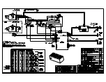
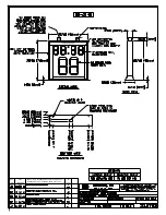
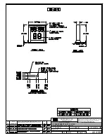
For advanced display troubleshooting and repair, it may be necessary to consult the
schematic drawings.
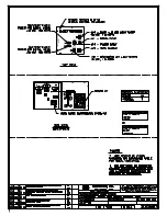
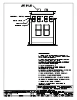
DWG-216653
shows detailed power and signal wiring diagrams of
internal display components such as drivers, transformers, and horns.
The schematic drawing also shows the DIP switch settings that control when the horn
sounds and when the LED light strips turn on.
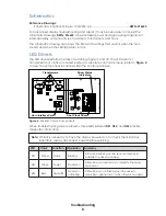
LED Drivers
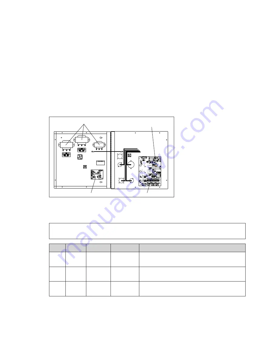
The LED driver performs the task of switching digits on and off. The LED driver for
transparent shot clocks is located inside of a separate control enclosure. Refer to
to view the component locations within the control enclosure.
HAZARDOUS VOLTAGE
BEFORE SERVICING
DISCONNECT POWER
Driver Status
Indicators
Shot Clock Driver
Horn Interface Card
Transformers
Figure 4:
Driver Enclosure Components
When troubleshooting driver problems, three LEDs labeled
DS1
,
DS2
, and
DS3
provide
diagnostic information.
Note:
While it is necessary to have the display powered on to check the LED status
indicators, always disconnect power before servicing.
LED
Color
Function Operation
Summary
DS1
Amber
Status
Blinking
DS1 will be blinking at one second intervals to
indicate the driver is running.
DS2
Green
Power
Steady on
DS2 will be on and steady to indicate the driver
has power.
DS3
Red
Signal RX
Steady on
or Blinking
DS3 will be on or blinking when the driver is
receiving a signal and off when there is no signal.
Summary of Contents for BB-2140
Page 4: ...This page intentionally left blank...
Page 18: ...This page intentionally left blank...
Page 19: ......
Page 20: ......
Page 21: ......
Page 24: ......
Page 25: ......
Page 26: ...AT EXPOSED TERMINALS HAZARDOUS VOLTAGE BEFORE SERVICING DISCONNECT POWER...
Page 27: ......
Page 28: ......
Page 31: ......
Page 32: ......
Page 33: ......
Page 34: ...This page intentionally left blank...


