DAKOTA ULTRASONICS PR-8V Operation Manual Download Page 18

Dakota Ultrasonics 

14 

AGC:

  The 

PR-8V

 is equipped with an automatic gain control when operating in 

echo-echo mode only.  This is much like turning the volume up or down on a stereo 
receiver.  However, the 

PR-8V

 will automatically control how much the volume is 

turned up or down.  Alternatively, the AGC can be manually controlled using the 
same procedures as GAIN described above.  Refer to page 51 for further info. 

Measure Mode:

  Used to select the measurement mode for different application 

requirements.  The modes are P-E (pulse-echo) and E-E(echo -echo). Refer to page 
22 for further info. 
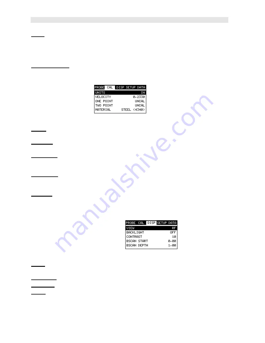
3.3 CAL – Menu  


Units:

  Toggle between English or Metric units.  The readout will change from inches 

to millimeters. 

Velocity:

   Function to calibrate the PR-8V by setting the velocity to a known material 

velocity.  Refer to page 34 for further info. 

One Point:

  Performs a single point calibration.  This option allows the user to 

automatically calculate the velocity by entering a known sample thickness. Refer to 
page 36 for further info. 

Two Point:

  Performs a two -point calibration.  This option allows the user to 

automatically calculate the velocity by entering a second known sample thickness. 
Refer to page 37 for further info. 

Material:

  Select the material velocity from a chart of basic material types, when a 

known sample thickness, or material velocity cannot be obtained. Refer to page 40 
for further info. 


3.4 DISP (display) – Menu   


View:

  Selectable RF wave, RECT (rectified) wave, BSCAN (cross section), and 

DIGITS (large digits) views. Refer to page 42 for further info. 

Backlight:

  Selectable OFF, ON, AUTO, or INVERT backlight option. 

Contrast:

  Adjustable display contrast for variable light conditions. 

B-ST:

  Provides the user the ability to change the start position o f the B-SCAN view. 

Refer to page 49 for further info. 

Summary of Contents for PR-8V

Page 1: ...OPERATION MANUAL DAKOTA ULTRASONICS P PR R 8 8V V Sonic Tester P N P 158 0002 Rev 1 10 January 2008...

Page 2: ......

Page 3: ...MENT MODE 25 CHAPTER SIX MAKING MEASUREMENTS 28 CHAPTER SEVEN USING THE DIGITS B SCAN DISPLAYS 41 CHAPTER EIGHT THRU PAINT MEASUREMENT TECHNIQUE 55 CHAPTER NINE ADDITIONAL FEATURES OF THE PR 8V 56 CHA...

Page 4: ......

Page 5: ...ics maintains a customer support resource in order to assist users with questions or difficulties not covered in this manual Customer support may be reached at any of the following Dakota Ultrasonics...

Page 6: ...all specific properties about the transducer Note Once the transducer has been selected the PR 8V will store and recall this transducer type every time the PR 8V is powered on off The type will only c...

Page 7: ...urn to the menu screen or ESC to cancel the selecting the transducer 2 2 Probe Zero Calibration The next step is to calibrate the PR 8V to the material and transducer being used If the materials sound...

Page 8: ...sk and proceed to the calibration section Note The value that is displayed will change depending on the current velocity setting in the PR 8V Disregard the number that is displayed It is not important...

Page 9: ...the sub menu items until VELOCITY is highlighted 3 Press the ENTER key to display the Digits Edit Box 4 Press the UP and DOWN arrow keys to scroll the highlighted value 5 Press the LEFT and RIGHT arr...

Page 10: ...ocedure 1 Physically measure an exact sample of the material or a location directly on the material to be measured using a set of calipers or a digital micrometer 2 Apply a drop of couplant on the tra...

Page 11: ...to scroll the digit locations 7 Repeat steps 5 6 until the known thickness value is correctly displayed 8 Press the OK key to calculate the velocity and return to the menu screen or ESC to cancel ente...

Page 12: ...activate the menu items tab Press the MENU key multiple times to tab right and the ESC key multiple times to tab left until the CAL menu is highlighted and displaying the submenu items 2 Use the UP a...

Page 13: ...through the sub menu items until VIEW is highlighted 3 Use the LEFT and RIGHT arrow keys to scroll the view options 4 Once the view is displayed press the MEAS key to return to measurement mode DIGIT...

Page 14: ...highlighted 2 Use the UP DOWN LEFT or RIGHT arrow keys to scroll the B ST and B DEP values 3 Repeat steps 1 2 until the range is correctly being displayed Alternatively the B ST and B DEP values can b...

Page 15: ...st method B SCAN DIGITS In the upper left corner of each of the mode photos above is the repeatability indicator The repeatability indicator is represented by six vertical bars and represents how repe...

Page 16: ...ab groups then contain sub menu items or functions The sub menu items have been organized in tab groups according to how closely they are related to the individual tab group names Let s first get fami...

Page 17: ...d Enter keys to scroll the options or activate the Digit Edit and List Box options The sections to follow will provide the user with an explanation of the sub menu functions 3 2 Probe Menu Zero The PR...

Page 18: ...fer to page 34 for further info One Point Performs a single point calibration This option allows the user to automatically calculate the velocity by entering a known sample thickness Refer to page 36...

Page 19: ...ct different languages for the PR 8V Refer to page 83 for further info 3 6 DATA Menu New Allows the user the ability to create a new alpha numeric grid with custom parameters rows and columns dependin...

Page 20: ...fer to page 59 for further info 3 8 XFER transfer Menu Backup Setups Enables the user the ability to backup the setups currently stored in the PR 8V to a PC via RS232 port Refer the help section of th...

Page 21: ...user with the ability to make crucial adjustments to the display waveform settings and grid storage locations without having to search through the menu and sub menu items It s important to first get...

Page 22: ...e LEFT and RIGHT arrow keys to scroll the digit locations 4 Repeat steps 2 3 until the delay width gain or threshold number is correctly displayed 5 Press the OK key to set and return to the measure s...

Page 23: ...ey toggles the measurement mode of the PR 8V from pulse echo flaw mode to echo echo thru paint mode This is a quick automatic preset mode that enables the user to change modes without having to manual...

Page 24: ...also used as a probe zero disk Simply remove the cover when replacing the batteries 3 AA cells When performing a probe zero function simply place the transducer on disk making firm contact Important...

Page 25: ...und Ultrasonic thickness measurement is practical in a wide variety of materials including metals plastics and glass Materials that are difficult include some cast materials concrete wood fiberglass a...

Page 26: ...iques are affected more than others For example dual element mode has larger errors due to changes in temperature of the delay line However multi echo techniques help to minimize these errors 4 6 Meas...

Page 27: ...e versus thickness relationship is non linear Therefore a correction table in the instruments software is used to compensate for this error Dual Element Transducer showing V path of signal Echo Echo M...

Page 28: ...generates a burst of ultrasound The PR 8V has a fixed repetition rate of 1 kHz or 1000 times per second The PR 8V updates the display 4 times per second in regular measurement mode and 32 times a seco...

Page 29: ...ese types of applications is pulse echo Dakota manufactures specific transducers for the racing industry The PR 8V has been optimized for cast materials Cast iron applications require a 5MHz frequency...

Page 30: ...e 7 5MHz and 10MHz models with extra resolution The higher frequencies provide greater resolution and a lower minimum thickness rating overall High temperature Use and select a special 2 25MHz and 5 M...

Page 31: ...Gn AGC Velocity 1 STEEL BASIC 5MHZ MED 0 2330 in uSec 2 STEEL THRU PNT STD 5MHZ HD AGC 0 2330 in uSec 3 STEEL THRU PNT EXT 3MHZ HD AGC 0 2330 in uSec 4 THRU PAINT RACING 5MHZ AGC 0 2330 in uSec 5 CAS...

Page 32: ...asuring curved materials it is more accurate to calibrate from two test points one at the minimum limit of the target thickness and one at the maximum limit In this case the reference disk mounted to...

Page 33: ...key to display the list of transducer types 4 Press the UP and DOWN arrow keys to scroll through the transducer list until the appropriate type is highlighted 5 Press the ENTER key to display the conf...

Page 34: ...er again after recalling a setup This will override the transducer saved with the setup 1 Press the MENU key once to activate the menu items tab Press the MENU key multiple times to tab right and the...

Page 35: ...ems or selected from a sub menu feature as follows Hot Menu Selection 1 Press the MEAS key once to activate measure menu items Press the MEAS key multiple times to move right and the ESC key multiple...

Page 36: ...As noted in chapter 3 the probe zero function is a very important and necessary function that must done prior to calibration It should also be done on a regular basis If the PR 8V is not zeroed corre...

Page 37: ...sub menu items until ZERO TRANSDUCER is highlighted 5 Press the ENTER key to display the confirmation screen 6 Press the OK key to zero the transducer and return to the menu screen or ESC to cancel t...

Page 38: ...he MENU key once to activate the menu items tab Press the MENU key multiple times to tab right and the ESC key multiple times to tab left until the CAL menu is highlighted and displaying the submenu i...

Page 39: ...PR 8V High Performance Thickness Gauge 35 8 Finally press the MEAS key to return to the measurement screen and begin taking readings...

Page 40: ...to the PR 8V s resolution of 001 0 01mm 2 Apply a drop of couplant on the transducer Place the transducer in steady contact on the known thickness location Be sure that the reading is stable and the r...

Page 41: ...ess the OK key to calculate the velocity and return to the menu screen or ESC to cancel entering the velocity 9 Finally press the MEAS key to return to the measurement screen and begin taking readings...

Page 42: ...f the display is fully lit and stable Press the MENU key once to activate the menu items tab Press the MENU key multiple times to tab right and the ESC key multiple times to tab left until the CAL men...

Page 43: ...lighted value 13 Press the LEFT and RIGHT arrow keys to scroll the digit locations 14 Repeat steps 12 13 until the known thickness value is correctly displayed 15 Press the OK key to calculate the vel...

Page 44: ...oll through the sub menu items until MATERIAL is highlighted 3 Press the ENTER key to display the list of Material Types 4 Press the UP and DOWN arrow keys to scroll through the material list until th...

Page 45: ...lind surfaces during a scan The B Scan display is also equipped with a scan bar representing the overall thickness Once again the scan bar gives the user a visual indication when a flaw or defect pass...

Page 46: ...3 Use the LEFT and RIGHT arrow keys to scroll the view options Once the appropriate view is displayed press theMEAS key to return to the measurement screen 7 2 Display Views DIGITS VIEW DIGITS The Dig...

Page 47: ...hash marks break the display up into 5 segments or quadrants The measurement labels correspond to the measurement at each hash mark G Scan Bar The scan bar corresponds directly with thickness represe...

Page 48: ...e that the measurement range on the display be set wide enough so that the maximum thickness of the material can be viewed on the display Using the diagram above if the material thickness was actually...

Page 49: ...lay As you can see from the diagram above the filled horizontal bar is displayed at 500 This display can be very useful when scanning materials in either B Scan or Digits display views It is much easi...

Page 50: ...outlined below Adjusting the Depth B DEP using the Hot Menus 1 Press the MEAS key once to activate measure menu items Press the MEAS key multiple times to move right and the ESC key multiple times to...

Page 51: ...the measurement screen or ESC to cancel entering the B DEP The user can also access and adjust the B DEP range from the tabbed menus However this method is a more tedious than making the adjustments u...

Page 52: ...ub menu items until BSCAN DEPTH is highlighted 3 Press the LEFT and RIGHT arrow keys to scroll the value When the correct width is being displayed proceed to step 8 4 Alternatively press the ENTER key...

Page 53: ...y on the back surface of the material and not possibly deeper than 200 In this case the user may wish to set the B ST at 700 to zoom in closer to the actual area being tested In turn the B DEP might b...

Page 54: ...Press the OK key to return to the measurement screen or ESC to cancel entering the B ST The user can also access and adjust the B ST from the tabbed menus However this method is more tedious than mak...

Page 55: ...the gain is crucial in order to obtain valid readings during the measurement process Too much gain may result in erroneous measurements by detecting on noise rather than the actual material back wall...

Page 56: ...When the echo echo thru paint measurement mode is selected the gain manual gain feature is disabled and grayed out in the menu items In this mode the PR 8V switches to an automatic gain mode AGC that...

Page 57: ...d theESC key multiple times to tab left until the PROBE menu is highlighted and displaying the submenu items 2 Use the UP and DOWN arrow keys to scroll through the sub menu items until GAIN is highlig...

Page 58: ...Dakota Ultrasonics 54 9 Finally press the MEAS key to return to the measurement screen and begin taking readings...

Page 59: ...thout coating The combination of using both modes is ideal for the advanced inspectors needs 8 2 Using Thru Paint Mode The first thing to note in this section is that by selecting the transducer type...

Page 60: ...s in all the clock positions of the cylinder the user can have some level of confidence that measurements obtained are representative of the individual cylinders in the block When the user is scanning...

Page 61: ...ety of applications to verify the material is within the manufacturer specifications There are two limits or alarm values that can be setup in the PR 8V ALARM LO LIMIT and ALARM HI LIMIT However the u...

Page 62: ...4 Continue on to the next section Setting the Alarm Lo Limit Setting the Alarm LO Limit 1 Assuming the ALARM STATUS is ON use the UP and DOWN arrow keys to scroll through the sub menu items until ALAR...

Page 63: ...EFT and RIGHT arrow keys to scroll the value When the correct alarm value is being displayed proceed to step 8 3 Alternatively press the ENTER key to display the Digits Edit Box 4 Press the UP and DOW...

Page 64: ...t clock position Multiple grids can be created and stored until the PR 8V s memory is full If the user attempts to store a grid in the PR 8V when the memory is full the PR 8V will respond with an erro...

Page 65: ...rid File Important Note This entire section is a step by step guide to successfully create a grid The instructions must be used in the sequential order specified as follows Creating a Grid Name 1 Pres...

Page 66: ...Use the UP DOWN LEFT RIGHT arrow keys to highlight the appropriate alpha characters 7 Press the ENTER key to select a character and advance to the next field of the Grid Name 8 Use the CLR key to back...

Page 67: ...hted 2 Press the ENTER key to activate the Alpha Edit Box 3 Use the UP DOWN LEFT RIGHT arrow keys to highlight the appropriate alpha characters 4 Press the ENTER key to select a character and advance...

Page 68: ...Therefore to define the top left corner of the grid there will be an X Y coordinate Where X is an alpha column location across the top and Y is a numeric row location down the side Use the same logic...

Page 69: ...2 Press the ENTER key to activate the Coordinate Edit Box 3 Use the LEFT RIGHT arrow keys to scroll the Columns and the UP DOWN arrow keys to scroll the Rows 4 Press the OK key to select the coordinat...

Page 70: ...roll the Rows 4 Press the OK key to select the coordinate and return to the Grid List Items screen or ESC to cancel the selection and return to theGrid List Items menu Note If there is not enough memo...

Page 71: ...rection to advance the cursor after storing a reading 5 Use the UP and DOWN arrow keys to scroll through the new Grid List Items until INCR DIR is highlighted 6 Use the LEFT RIGHT arrow keys to toggle...

Page 72: ...set the user has the option of saving or canceling the new grid 1 Use the UP and DOWN arrow keys to scroll through the new Grid List Items until CREATE NEW GRID is highlighted 2 Press the ENTER key to...

Page 73: ...ted it s time to make some measurements and store the readings The following procedures outline this process Storing a Reading Note In the photos above the MEM format is set to GRID However if the ENG...

Page 74: ...ading in the highlighted cell location 6 Abort the Grid View Box by pressing the MEAS key at any time Note Every time a reading is saved to memory a picture of the display is automatically saved with...

Page 75: ...display the Grid View Box 3 Press the UP DOWN LEFT and RIGHT arrow keys to scroll the stored readings and corresponding display view Notice as the cursor is moved to a different cell the display will...

Page 76: ...laying the submenu items 2 Use the UP and DOWN arrow keys to scroll through the sub menu items until DELETE ONE FILE is highlighted 3 Press the ENTER key to display the Grid List Box 4 Use the UP and...

Page 77: ...d DOWN arrow keys to scroll through the sub menu items until DELETE ALL FILES is highlighted 3 Press the ENTER key to activate the confirmation screen 4 Press the OK key to delete All Files from memor...

Page 78: ...ed and displaying the submenu items 2 Use the UP and DOWN arrow keys to scroll through the sub menu items until EDIT is highlighted 3 Press the ENTER key to display the Edit List Box 4 Use the UP and...

Page 79: ...used when editing the NOTE 6 Use the UP DOWN LEFT RIGHT arrow keys to highlight the appropriate alpha characters 7 Press the ENTER key to select a character and advance to the next field of the Comme...

Page 80: ...8 Changing the active grid File Open The user may have transferred grid templates from a PC to the PR 8V or setup grids using the PR 8V at an earlier time The name of the currently active grid is alwa...

Page 81: ...tab left until the DATA menu is highlighted and displaying the submenu items 2 Use the UP and DOWN arrow keys to scroll through the sub menu items until OPEN is highlighted 3 Press the ENTER key to di...

Page 82: ...Dakota Ultrasonics 78 6 Press the OK key to load the grid from memory 7 Press the MEAS key to return to the measure screen...

Page 83: ...ed at any time The PR 8V can store 64 custom setups These setups can be bi directionally transferred to and from a PC Therefore the user can save as many setups as necessary for all of the individual...

Page 84: ...SC key multiple times to tab left until the SETUP menu is highlighted and displaying the submenu items 2 Use the UP and DOWN arrow keys to scroll through the sub menu items until OPEN is highlighted 3...

Page 85: ...ecific setup location for future use This can potentially save time and reduce error between users It is sometimes necessary to rename a previously saved setup or add additional comments about a parti...

Page 86: ...key multiple times to tab left until the SETUP menu is highlighted and displaying the submenu items 2 Use the UP and DOWN arrow keys to scroll through the sub menu items until SAVE is highlighted 3 Pr...

Page 87: ...s the OK key to return to the Save Setup Parameters List Box 8 If both parameters will be edited repeat steps 4 7 9 Use the UP and DOWN arrow keys to scroll to and highlight SAVE SETUP 10 Press the EN...

Page 88: ...file in the PR 8V was somehow corrupted and the user does not have access to a computer to re load the factory setups back into the PR 8V This gives the user the ability to load and modify a basic set...

Page 89: ...h Performance Thickness Gauge 85 Important Note Remember to perform a probe zero function prior to measuring The default setup clears the probe zero value 4 Press the OK key to return to the measureme...

Page 90: ...iew requires an available communications port in order to transfer data to and from the PR 8V PR 8Vsonicview or PR 8Vview supports COM1 COM2 COM3 and COM4 USB to Serial Converter Some newer laptop com...

Page 91: ...0 1280 3251 Inconel 0 2290 5817 Iron 0 2320 5893 Cast Iron 0 1800 approx 4572 Lead 0 0850 2159 Magnesium 0 2300 5842 Mercury 0 0570 1448 Molybdenum 0 2460 6248 Monel 0 2110 5359 Nickel 0 2220 5639 Nyl...

Page 92: ...Dakota Ultrasonics 88 Tin 0 1310 3327 Titanium 0 2400 6096 Tungsten 0 2040 5182 Uranium 0 1330 3378 Water 0 0580 1473 Zinc 0 1660 4216 Zirconium 0 1830 4648...

Page 93: ...STEEL BASIC 5MHZ MED 0 2330 in uSec 2 STEEL THRU PNT STD 5MHZ HD AGC 0 2330 in uSec 3 STEEL THRU PNT EXT 3MHZ HD AGC 0 2330 in uSec 4 THRU PAINT RACING 5MHZ AGC 0 2330 in uSec 5 CAST IRON BASIC 5MHZ M...

Page 94: ...A Stability Stable Conditions to Avoid none Incompatibility Materials to Avoid none known Hazardous Polymerization will not occur Hazardous Decomposition or Byproducts none known SECTION 6 HEALTH HAZA...

Page 95: ......

Reviews: