background image


3.


Installation


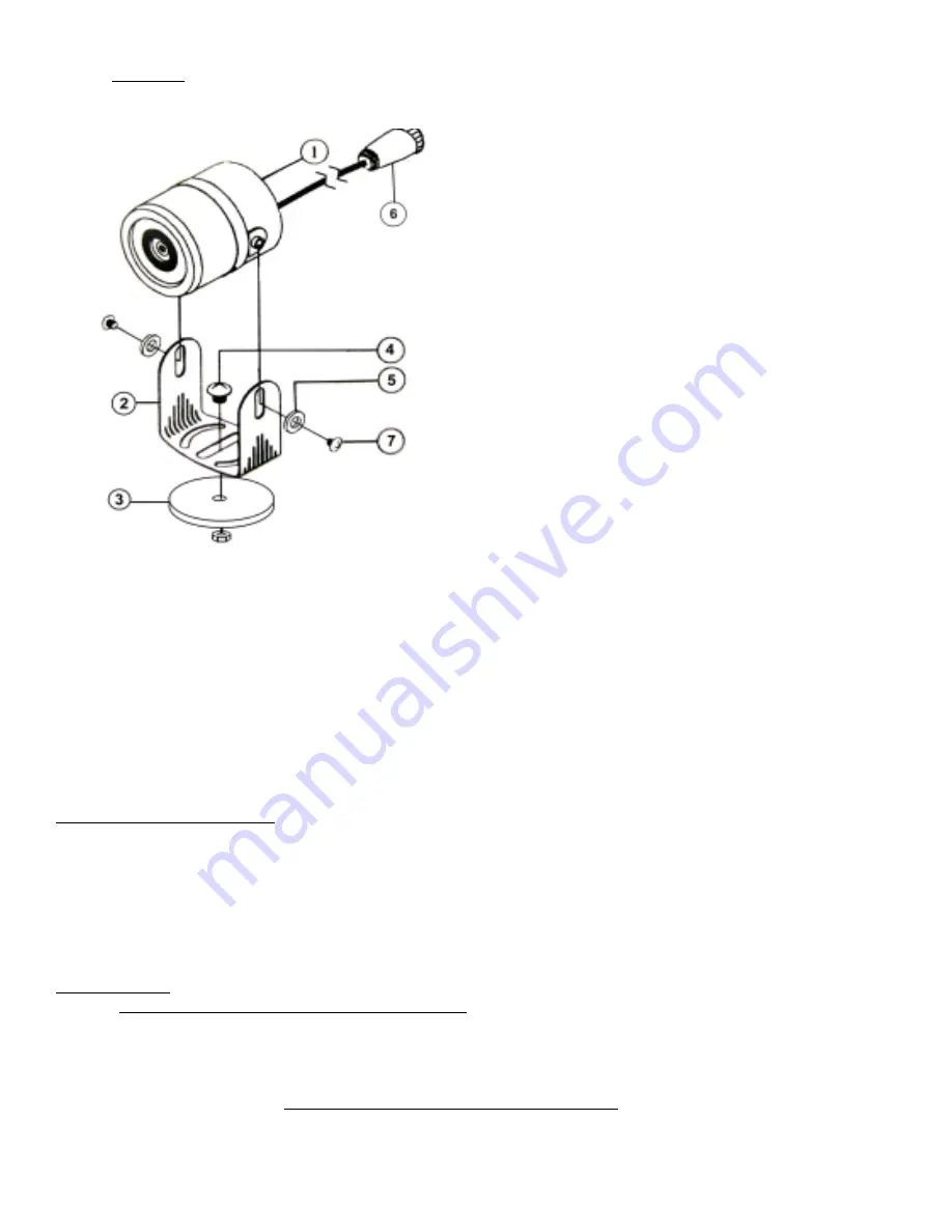
a.


Camera


Installation


&


Mounting


1.


Camera


Body


2.


Mounting


Bracket


3.


Magnetic


Base


4.


Retaining


Screw


5.


Fiber


Washer


6.


Power/Video


Input


7.


Bracket


Screw


Temporary


Mount:


For


temporary


mounting,


it


is


recommended


that


you


use


the


supplied


#25


pull


magnet.


If


using


magnetic


mount,


fasten


camera


cable


with


a


zip


tie


or


other


style


fastener.


This


will


act


as


a


“safety


wire”


in


the


event


your


camera


is


knocked


loose


for


some


reason.


When


selecting


a


location,


make


sure


that


the


equipment


surface


is


clean


of


all


foreign


material


and


as


flat


as


possible


to


ensure


that


the


magnetic


camera


base


will


have


good


contact


and


not


vibrate


off.


Permanent


Mount:


For


permanent


mounting,


it


is


recommended


that


you


remove


the


magnet


and


attach


to


any


solid


surface


with


two


(2)


screws.


After


camera


is


securely


mounted,


plug


Power/Video


Input


(6


in


above


diagram)


into


AgCam®


extension


power/video


cable.


Make


sure


they


are


securely


attached


and


locked


turn


will


lock


the


cables


together).


Suggestions


for


Mounting


Camera:


When


determining


the


location


for


the


camera


it


is


always


best


to


use


a


solid


surface


to


minimize


vibration.


Ladders


are


not


good


mounting


choices


due


to


lack


of


stability.


If


you


will


be


using


your


AgCam®


for


assisting


in


visibility


for


implement/vehicle


towing,


you


will


want


to


position


the


camera


so


you


can


see


the


desired


area


and


a


portion


of


the


vehicle


in


tow,


this


will


give


you


some


reference


to


distance.


You


will


also


want


to


use


the


mirrored


setting


in


the


monitor


menu


so


as


to


accurately


represent


left


and


right


(this


will


give


you


the


effect


of


looking


in


a


rear


view


mirror).


Camera


Warnings


NEVER


RELY


ON


YOUR


AGCAM®


AS


A


SAFETY


FEATURE.


It


is


up


to


your


discretion


to


keep


your


road


travel


and


other


operations


safe.


Your


AgCam®


will


provide


you


with


information


only


based


on


what


it


sees.


Operation


of


machinery


safety


guidelines


still


apply.


The


AgCam®


is


equipped


with


an


array


of


infrared


light


emitters


which


are


invisible


to


the


human


eye.


This


feature


will


aid


in


low


light


conditions


but


has


limitations.


The


effective


range


of


the


night


vision


feature


is


1


to


40


feet


and


will


produce


a


monochrome


image


only.


Do


not


attempt


to


drive


machinery


using


this


feature


b.


Cable


Installation


&


Mounting


Summary of Contents for DMAC?9M?C1

Page 1: ...Mounting 4 b Cable Installation Mounting 4 5 c Monitor Installation Mounting 5 7 4 Monitor Remote Operation 7 8 5 Standard Menu Settings 8 9 6 Digital Video Tuner Settings 9 11 7 Hidden Menu Settings...

Page 2: ...tents 1 Monitor 2 Monitor Base 3 Monitor Remote 4 A C power adaptor style may vary 5 12v Hardwire kit 6 A V In Out Cable 7 Misc Accessories not shown Camera Kit Contents 1 Camera w bracket magnetic ba...

Page 3: ...light conditions This lens is also transparent of infrared light allowing the LED s to penetrate even when it is darkened Standard lens features 92 field of view 3 6mm Optional lenses available includ...

Page 4: ...hen determining the location for the camera it is always best to use a solid surface to minimize vibration Ladders are not good mounting choices due to lack of stability If you will be using your AgCa...

Page 5: ...ended that you use bolts to secure the camera While it would be sufficient to use the magnetic base for monitoring purposes during road travel it is advised to secure the camera with bolts during oper...

Page 6: ...adaptor RIGHT ABOVE the cigarette lighter adaptor 2 Split with stripe and black wires 3 Strip both wires to expose approx bare wire 4 Insert with stripe into RED male Scotchlok and crimp 5 Insert blac...

Page 7: ...eft Right all arrows INFO ONLY RETURN Switches to the last channel you were viewing TV AV Provides basic setting info SOUND Non Functional GUID Volume Adjust CC ON Channel Info C A CC ON OFF FORMAT Ch...

Page 8: ...lighted item 3 To exit a Press MENU key on the monitor multiple times till the menu goes away b Press EXIT on the remote c Allow monitor to time out approximately 5 seconds PICTURE BRIGHT Adjusts the...

Page 9: ...r your country Auto PAL NTSC or SECAM US only should always be on Auto or NTSC Any other setting might cause distortion CLOCK SLEEP Set how many minutes before the monitor automatically turns off TIME...

Page 10: ...t to add or remove Skip Selecting ON will remove the channel from memory Selecting OFF will allow the channel to be viewed CC SETUP Settings for Closed Captioning CC CC Display Turn CC on or off 608CC...

Page 11: ...mately 5 seconds for it to enable itself You cannot switch back to VIDEO1 till this process has completed Be very cautious while using this menu An improper setting may make your monitor unusable or r...

Page 12: ...setting LOGO S set to 1 if you would like to show a logo that you define below LOGO C Text color of the logo you define below 1 Blue 2 Green 3 Yellow 4 Red 5 Cyan 6 Yellow 7 White LOGO E Enter the te...

Page 13: ...ce 2 1 Gamma Characteristic 0 45 Lenses Furnished Board Lens 3 6mm F2 0 Photogray Body Lens Synchronous System Internal Negative sync Back Light Compensation On Off Switch able Video Output 1 Vp p 75...

Page 14: ...anties beyond the time period described herein on behalf of Dakota Micro Inc The warranties described herein shall be the sole and exclusive warranties granted by Dakota Micro Inc and shall be the sol...

Page 15: ...mp cleaning cloth or soft camera lens brush Our photo gray camera lenses have been made impact resistant and have been drop ball tested according to Sec 3 84 21 CRF BUT ARE NOT UNBREAKABLE Because the...

Page 16: ...Inc products specifications pricing and programs are subject to change without prior notice Dakota Micro Inc reserves the right to make design changes at any time without obligation to retroactively...

Reviews: