2
MAN # 650702
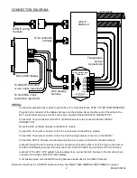
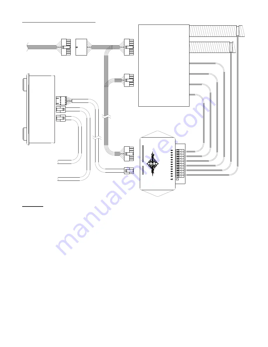
CONNECTION DIAGRAM:
- CABIN
+ CABIN
STATUS LED
- DEFROST
+ DEFROST
- FLOOR B
+ FLOOR B
- FLOOR A
+ FLOOR A
- VENT B
+ VENT B
- VENT A
+ VENT A
www.dakotadigital.com
605-332-6513
D
IS
P
L
A
Y
C
O
N
N
E
C
T
O
R
G
E
N
-IV
C
O
N
N
E
C
T
O
R
DCC CONTROL BOX
FOR GEN-IV
GEN IV
MODULE
WIRING:
Connect temperature sensor wires to control box. (For more details see STEP 7: WIRE TEMP SENSORS)
Plug the 5 pin connector of the Display Harness into the display. Route the other end of the cable to the
DCC-control box and plug it into the control box connector labeled “DISPLAY CONNECTOR.”
Connect the 14 pin connector of the DCC controller harness to the connector labeled “GEN-IV
CONNECTOR”.
Route the DCC controller harness to the GEN-IV module.
Connect the 12 pin wire connector to the 12 pin connector on the GEN-IV module.
Connect the 16 pin wire connector to the 16 pin main wiring harness connector on the GEN-IV.
Connect the GEN-IV harness into the remaining 16 pin connector on the DCC controller harness.
(optional*) Using the HLC harness (2 six pin connectors) connect to either one of the 6 pin connectors on
the DCC-4000 display. Connect the other end to the “CLOCK CABLE” port on HDX or RTX control box.
(optional*) If the HDX / RTX system has an analog clock, connect its HLC harness to the remaining 6 pin
connector on the back of the DCC-4000 display.
If not already wired, wire the GEN-IV wiring harness as described in the GEN-IV manual.
*Optional connections for HDX/RTX theme matching. See NIGHT TIME DIMMING AND THEMES on page 7.
DCC-4000 display
DCC display
harness
Temperature
sensor
connections
GEN IV wiring
harness
Vent hoses
DCC controller
harness
To HDX/RTX Control
CLOCK CABLE
(optional*)
To HLC/RLC clock
connection (optional*)


