background image

Dake Corporation 

724 Robbins Road  

Grand Haven, MI 49417 

www.dakecorp.com


  7 

REV022019 


SET UP 


ASSEMBLY 


Motor Pulley Cover: (Items 290, 291, 293, 294, & 343) 


1)  Open the cover and slide the bottoms openings around the pulleys.


2)  Line up the holes in the motor pulley case with the hole in the bracket coming up from the 

motor mount bracket. 

3)  Use the washers and hex screws to attach the cover to the bracket in the center and 

righthand side of the cover. 

4)  Close cover and snap lower fastener closed, then use the washer and round head screw 

to keep it securely closed. 


Wheels: (Items 94-96) 


1)  Take the wheel rods and slide them though the holes at the bottom of the saw stand. See 

exploded parts view as reference.


2)  Pace a wheel on each end of the rods.


3)  Use a cotter pin and insert it through the hole in the end of the rod to secure the wheels.


BLADE SELECTION  


An 8-tooth per inch general use blade comes installed with this metal cutting bandsaw. 

Additional blades in 4, 6, 8, and 10 tooth pitches are available. However, 3 teeth should be 

engaged with the workpiece at all times for proper cutting. 
For maximum cutting efficiency and lowest cost per cut, it is important to select the blade with 

the correct number of teeth per inch (TPI) for the material being cut. The material size and 

shape dictate tooth selection. 
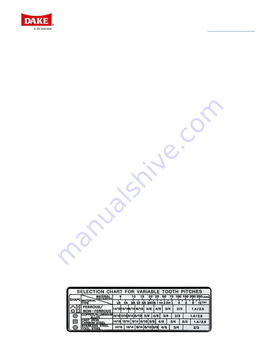
Located on the saw is a chart to determine the tooth pitch or TPI needed for cutting various 

material types and shapes. 
For piping, tubing, and structural the material thickness used is the average thickness that the 

blade goes through during the cut. 


Summary of Contents for SE-712

Page 1: ...3253 www dakecorp com customerservice dakecorp com DAKE METAL CUTTING HORIZONTAL BANDSAW Model SE712 INSTRUCTIONAL MANUAL WARNING Read and understand all instructions and responsibilities before oper...

Page 2: ...ION 8 VICE 8 WORK STOP ADJUSTMENT 10 CONTROLS 10 CHANGING FEED RATE 10 OPERATING 11 CHANGING BLADE SPEED 11 VERTICAL CUTTING 12 MAINTENANCE 13 PERIODICAL MAINTENANCE 13 BLADE REMOVAL AND INSTALLATION...

Page 3: ...communication has been initiated Dake Customer Service must be contacted for approval Phone 800 937 3253 Email customerservice dakecorp com When contacting Dake please have the following information r...

Page 4: ...Customer Service a representative will supply a Return Material Authorization RMA number The returned item must have the provided RMA number clearly marked on the outside packaging Any item received w...

Page 5: ...5 capacity 3 1 4 x 5 1 2 Max blade speed 235 fpm Bed work area 21 x 9 Blade width 3 4 Weight 355 lbs Blade length 93 Floor space 51 x 16 Blade speeds fpm 85 130 180 235 Floor to bed 21 3 4 In the spac...

Page 6: ...sed for any other application Machine is intended to be operated by one person This person should be conscious of the saws operations not only for themselves but also for persons in the immediate area...

Page 7: ...Keep work area well lit Do not install or use machine in explosive or dangerous environment Keep visitors away from tool Anyone unqualified to run the tool should have no interaction with the tool Mai...

Page 8: ...parts view as reference 2 Pace a wheel on each end of the rods 3 Use a cotter pin and insert it through the hole in the end of the rod to secure the wheels BLADE SELECTION An 8 tooth per inch general...

Page 9: ...rass 180 246 150 203 Aluminum Plastic 235 328 195 270 COOLANT Use a water soluble coolant Coolant is mixed 10 1 10 parts water to one part coolant Once the coolant is mixed pour it into the tray and l...

Page 10: ...ng the gauge near the top of the vice then tighten Bolts C and D 3 Slide the left jaw of the vice to meet the right to match the angle then tighten bolts A and B 4 The left jaw can then be operated as...

Page 11: ...on the front right of the saw is the adjustment for the feed rate as well as the down feed lock To slow the feed rate turn the knob clockwise counterclockwise causes the feed to increase Feed can be...

Page 12: ...aw is up to full speed release the head stop to let the saw gravity feed down into the workpiece a Never force the saw into the work this could damage the saw as well as the work 6 Once the saw has ma...

Page 13: ...valve 3 Remove the 2 cross head screws item 272 and the deflector plate item 271 that are located on the rear blade adjustable item 262 Set aside the deflector plate for later use 4 Take the vertical...

Page 14: ...eel cover item 287 by pulling up and sliding it out from its position 2 Open the blade guards by unscrewing the two knobs on backside of the blade guard item 284 3 Loosen the blade tensions knob count...

Page 15: ...o a new blade in to see if it will correct the poor cutting before beginning to adjust the guides The guides should have 000 just touching to 001 of clearance between themselves and the blade 1 The ou...

Page 16: ...eed pressure Adjust blade speed and or feed pressure See BLADE SPEED and CHANGING FEED RATE sections in manual Blade teeth spacing too large Replace with higher TPI blade Material is too coarse Slow d...

Page 17: ...Blade guides worn Replace blade guides Blade guide bearings not adjusted properly Readjust guide bearings See BLADE GUIDE BEARING ADJUSTMENT section of manual Blade guide bearing bracket is loose Tigh...

Page 18: ...heck oil path Cut is binding blade Decrease feed pressure Blade not cutting straight Feed pressure is too high Reduce feed pressure by increasing the spring tension on side of saw Feed pressure is too...

Page 19: ...rt Name Qty Part No Part Name Qty 301461 Electrical box 1 716558 Coolant on off button 1 301462 Connector 24 volt 1 716540 Start button green 1 301795 Overload 1 716539 Stop button red 1 300828 Relay...

Page 20: ...Dake Corporation 724 Robbins Road Grand Haven MI 49417 www dakecorp com 19 REV022019 EXPLODED VIEW PARTS LIST EXPLODED PARTS VIEW Limit Switch 300733...

Page 21: ...Dake Corporation 724 Robbins Road Grand Haven MI 49417 www dakecorp com 20 REV022019...

Page 22: ...0 Hex Socket Head Screw 3 8 16 x 1 1 2 1 18 43916 N001 Hex Nut 1 2 13 1 19 300907 W002 Washer 1 2 2 20 302492 S501 Carriage Screw 1 2 12 x 2 1 21 302491 S003 Hex Head Screw 1 2 12 x 2 1 22 300939 1811...

Page 23: ...43881 S708 Cross Round Head Screw 10 24 x 3 8 2 61 300733 Limit Switch Assembly of parts 55 56 58 388 1 62 301537 181106 Coolant Pan 1 63 181989 Switch Bracket For CE Only 1 64 43881 S708 Cross Round...

Page 24: ...6 12 2 115 43881 S708 Cross Round Head Screw 10 24 x 3 8 2 116 301695 192029 Bearing Spacer 1 117 301696 181307 Bushing 1 118 78744 HS422 Hex Socket Headless Screw M6 x 10mm 1 301620 181241BS Brush as...

Page 25: ...pring Washer 3 8 4 229 43330 S013 Hex Socket Head Screw 3 8 16 x 1 1 4 4 Not Shown C Retainer ring 26 PT 231 300947 181214 2 Drive Wheel 1 232 43314 S022 Hex Head Screw 5 16 18 x 3 4 1 234 236 301730...

Page 26: ...asher 5 16 1 270 43316 S416 Hex Socket Head Screw 5 16 18 x 1 1 4 1 271 301602 3069 Deflector Plate 1 272 43798 S301 Flat Cross Head Screw 1 4 20 x 1 2 2 273 300746 181243 Bearing Shaft 2 274 300745 1...

Page 27: ...Washer 5 16 8 307 301709 181233A Motor Mount Bracket 1 310 301484 S201 Cross Round Head Screw 1 4 20 x 1 2 2 311 43631 W005 Washer 1 4 2 312 301802 181232 1 Support Plate 1 313 301486 3055 3 Vertical...

Page 28: ...5 Hex Nut 3 8 16 1 356 181979 Hose Bib 1 357 43632 W018 Flat Washer 5 16 2 358 43314 S022 Hex Head Screw 5 16 18 x 3 4 2 371 ET1304 Wire Nipple 1 2 2 375 43881 S708 Cross Round Head Screw 10 24 x 3 8...

Reviews: