background image

4123 Series User Manual

Models/Components

D004-000017

29

1

1

2

2

3

3

4

4

5

5

6

6

7

7

8

8

A

A

B

B

C

C

D

D

SH

EET

 2 


O

F

 2 

SI

ZE

D

SC

AL

E

REV

01

TH

IS

 D

O

CU

ME

NT 

IS

 C

O

NSI

DE

RE

D

PR

OPRI

ET

AR

TO

 D

DI

SP

LA

YS

, I

NC

.  

TH

US

OR 

RE

PRO

DUC

TION

 O

F

TH

IS

 D

O

CU

ME

NT 

IS

 P

RO

HIBI

TE

D

EX

CEP

T A

S A

UT

HO

RI

ZE

D B

TH

CO

RP

ORA

TION 

IN

 W

RITIN

G.

SP

EC

IF

IC

AT

IO

NS 

AR

SUBJ

EC

T

TO

 C

HANGE

 W

ITH

O

UT 

NOT

IC

E.

TO

LERA

NC

ES

DI

M

ENS

IO

N

S AR

E

IN

 I

N

CH

ES

DR

AW

N

CH

EC

KED

FR

AC

TIO

NS



/32

"

DE

CI

M

AL

S

.X

=




03

.X

XX 

=




015

ANG

LES



G. 

DR

AP

CHO

J.

 KU

YK

ENDALL

AP

PR

O

VAL

DA

TE

CU

ST

 D

W

G,

41

23

AF

,W

KS

,M

OB

IL

E,

NI

TIT

LE

DW

NO

2850 

Lew

isb

er

ry 

Ro

ad

Yo

rk 

Ha

ven

, P

17370

Ph

one

: 7

17

.9

32

.99

99

Vi

sit

 u

at

w

w

w

.d

3i

nc

.n

et

9/

12

/2

018

6/

19

/2

018

D302-000420

1/4-20 

.500 

UNC


SO

CKE

HE

AD 

FL

AT

SS 

MA

CH

INE 

SC

REW

Q

TY 

(2)

1/

4-20 

.500 

UNC


SO

CK

ET

 H

EA

FL

AT


SS 

MA

CHIN

SC

REW

QT

(2

)

1/

4-20 

.375 

UN

SO

CK

ET

 HEA

D

CA

P L

O

W

 P

RO

FI

LE

SS 

SC

RE

W

QT

(2)

1/4-20 

.375

 UNC


SO

CKE

HE

AD

CA

LO

PR

OF

IL

E

SS 

SC

REWS 

Q

TY

 (2

)

1.13

2.0

0

2.0

0

2.0

0

1.13

2.0

0

3.88

3.88

1.13

1.13

3.88

3.88

.00

.51

.73

3.7

0

3.8

1

4.1

3

4.5

3

4.9

4

5.2

5

5.4

7

6.0

0

6.5

3

6.7

5

7.6

0

9.1

0

9.7

5

10.

45

11.

25

11.

70

12.

69

12.

80

15.

77

15.

98

.0

0

.5

2

.7

3

1.65

1.78

2.59

2.72

4.17

4.30

5.25

5.45

5.80

7.42

7.50

9.05

9.39

9.76

10.55

10.67

12.02

12.24

2.0

0

2.1

6

5.1

2

11.

37

14.

34

14.

50

10-32 

.375 

UNF T

ORX

PAN

 H

EA

SS

 M

AC

HI

NE

SC

REW

Q

TY

 (22)

6-

32

 x

 .3

75

 U

NC

 T

OR

X

PA

HE

AD 

SS 

M

ACHINE

SC

RE

W

Q

TY 

(1

6)

10-32 

UNF 

VE

SA

M

OUN

HO

LE

S

6.2

8

10.

22

3.2

4

5.7

4

8.2

5

10.

76

13.

26

REVISI

ON

 H

ISTO

RY

ZO

NE

RE

V

DE

SC

RIP

TION

DA

TE

APR

N/A

01

ADD

ED 

M

AT

ERIAL 

AN

HA

RDWA

RE 

DETA

ILS 

DIMS, 

ADDE

SHEE

2

9/

6/2018

JL

K

1.37

1.50

2.19

2.87

3.00

4-40 

.375 

UNC 

PH

ILLIP

S

PA

HE

AD

 SS 

MA

CH

INE

SC

RE

W

Q

TY 

(8)

6-32 

.3

75 

UN

TOR

X

PA

HEAD 

SS 

MA

CH

INE

SC

REWS 

QTY

 (16)

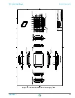
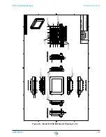
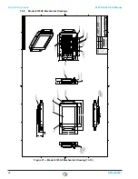
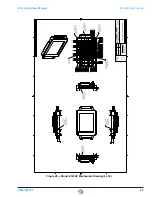
Figure 28 — Model 4123AF Mechanical Drawing (2 of 2)

Summary of Contents for 4123 Series

Page 1: ...i7 128GB Slim Sata 16GB RAM Battery B U 4123AC Cast Aluminum Intel Core i7 256GB 2 5 SSD 16GB RAM WiFi 4123AD Cast Aluminum Intel Atom 128GB Slim Sata 8GB RAM Wi Fi 4123AE Cast Aluminum Intel Core i7...

Page 2: ...peripherals manufactured by Daisy Data Displays generate use and can radiate radio frequency energy and if not installed and used in accordance with the instructions in this manual may cause interfer...

Page 3: ...r warranty of quality whether expressed or implied except of title and against patent infringement Correction of nonconformities in the manner and for the period of time provided above shall constitut...

Page 4: ...Diagram 15 7 5 2 Model 4123AC Block Diagram 16 7 5 3 Model 4123AD Block Diagram 17 7 5 4 Model 4123AE Block Diagram 18 7 5 5 Model 4123AF Block Diagram 19 7 6 Model 4123 xx Series Mechanical Drawings...

Page 5: ...to be used in a variety of locations While adhering to the stringent design parameters to meet the Zone 2 hazardous location rating Daisy Data Displays has engineered the core functionality of the Mod...

Page 6: ...rt team can help you with installation configuration troubleshooting and other support issues for all Daisy s products 3 0 Software Hardware Daisy data should be contacted for any hardware or software...

Page 7: ...Zone 2 Protection Methods 0 C Ta 40 C Model 4123 Only Operating Temperature Range 20 C Ta 55 C Models 4123AC 4123AD 4123AE 4123AF 4 1 Model 4123 Special Conditon Due to the front enclosure on the Mode...

Page 8: ...N 61000 4 5 EN 61000 4 6 EN 61000 4 11 EN 60950 1 2006 A11 2009 A12 2011 A1 2010 A2 2013 EN IEC 60079 0 2017 EN IEC 60079 1 2014 EN IEC 60079 7 2017 EN IEC 60079 15 2017 IEC 60529 ed 2 2 Dated 2013 08...

Page 9: ...C is based upon five 5 unique base models incorporating a standard set of components options for each model In addition to the standard components options each model has a specific glandplate designed...

Page 10: ...n i7 module E905 000017 14 4V Smart Battery 4123AC P010 000101 110VAC Power Supply P310 005000 Motherboard COM Express carrier board P000 000139 15 LCD Display P040 000098 15 Projected Capacitance Tou...

Page 11: ...el i7 6th gen Module P060 000099 Storage 256GB 2 5 SSD A314 418000 8GB DDR4 Memory used with 6th gen i7 module 4123AF P010 000101 110VAC Power Supply P310 005000 Motherboard COM Express carrier board...

Page 12: ...gned for it as shown in Table 3 See Table 5 below for the connections assigned to each glandplate Table 5 4123 xx UL Listed ATEX Zone 2 Certified Glandplate Configurations Gland Assembly Includes I640...

Page 13: ...d making all external connections In addition care must be taken when making the external connections to the Model 4123xx The unit MUST be de enegized and or the location rendered a non hazardous area...

Page 14: ...10 D004 000017 Models Components 4123 Series User Manual 7 4 2 Model 4123AC Field Wiring Diagram Figure 9 Model 4123AC Field Wiring Diagram...

Page 15: ...4123 Series User Manual Models Components D004 000017 11 7 4 3 Model 4123AD Field Wiring Diagram Figure 10 Model 4123AD Field Wiring Diagram...

Page 16: ...12 D004 000017 Models Components 4123 Series User Manual 7 4 4 Model 4123AE Field Wiring Diagram Figure 11 Model 4123AE Field Wiring Diagram...

Page 17: ...4123 Series User Manual Models Components D004 000017 13 7 4 5 Model 4123AF Field Wiring Diagram Figure 12 Model 4123AF Field Wiring Diagram...

Page 18: ...ed configuations as described in 7 1 Base Model 4123 Series Configurations on page 5 The following block diagrams detail each of the base models and the components contained in each Model 4123 Block D...

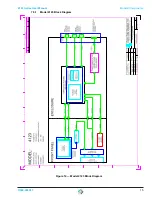
Page 19: ...4123 Series User Manual Models Components D004 000017 15 7 5 1 Model 4123 Block Diagram Figure 14 Model 4123 Block Diagram...

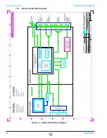
Page 20: ...16 D004 000017 Models Components 4123 Series User Manual 7 5 2 Model 4123AC Block Diagram Figure 15 Model 4123AC Block Diagram...

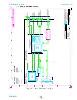
Page 21: ...4123 Series User Manual Models Components D004 000017 17 7 5 3 Model 4123AD Block Diagram Figure 16 Model 4123AD Block Diagram...

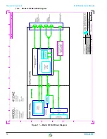
Page 22: ...18 D004 000017 Models Components 4123 Series User Manual 7 5 4 Model 4123AE Block Diagram Figure 17 Model 4123AE Block Diagram...

Page 23: ...4123 Series User Manual Models Components D004 000017 19 7 5 5 Model 4123AF Block Diagram Figure 18 Model 4123AF Block Diagram...

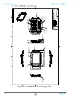
Page 24: ...1 31 2 25 4 41 4 61 CARBON FIBER TWILL WEAVE FACE PLATE CARBON FIBER TWILL WEAVE REAR PLATE ENCLOSURE 6061 T6 AL POWER CABLE GLAND MANUF SEALCON P N CD13NA EX ETHERNET MANUF AMPHENOL PCD P N RJFTV21N...

Page 25: ...10 45 11 25 11 70 12 69 12 80 15 77 15 99 00 52 73 1 61 1 70 2 67 2 76 2 99 4 17 4 30 5 25 5 80 7 42 7 50 9 05 9 76 10 55 10 67 12 02 12 24 00 2 00 10 75 00 1 13 1 4 20 x 500 UNC FLAT HEAD SOCKET SS...

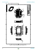
Page 26: ...932 9999 Visit us at www d3inc net 9 12 2018 6 19 2018 D302 000421 4 65 1 19 16 72 12 97 CAST A356 2 AL REAR PANEL REVISION HISTORY ZONE REV DESCRIPTION DATE APR N A 01 ADDED MATERIAL AND HARDWARE DE...

Page 27: ...1 ADDED MATERIAL AND HARDWARE DETAILS DIMS ADDED SHEET 2 8 29 2018 JLK DRAFT FACE VIEW DRAFT FACE VIEW DRAFT FACE VIEW DRAFT FACE VIEW 1 14 1 68 1 68 1 14 1 68 1 68 18 18 1 14 18 18 1 14 1 4 20 x 500...

Page 28: ...s at www d3inc net 9 12 2018 8 29 2018 USB A INPUT MANUF USB FIREWIRE P N RR 211300 03 Z6C POWER CORD GRIP MANUF SEALCON P N CD21NR EX 21 33 12 97 16 72 4 39 2 25 3 30 ETHERNET RJ45 NETWORK INPUT MANU...

Page 29: ...ON DATE APR N A 01 DETAILED MATERIALS ADDED SHEET 2 8 29 2018 NGW DRAFT FACE VIEW DRAFT FACE VIEW DRAFT FACE VIEW DRAFT FACE VIEW 00 1 68 10 43 00 1 14 00 94 00 18 8 93 00 18 8 93 00 1 14 00 1 14 00 1...

Page 30: ...s at www d3inc net 9 12 2018 8 29 2018 USB A INPUT MANUF USB FIREWIRE P N RR 211300 03 Z6C POWER CORD GRIP MANUF SEALCON P N CD21NR EX 21 33 12 97 16 72 4 39 2 25 3 30 ETHERNET RJ45 NETWORK INPUT MANU...

Page 31: ...1 68 10 43 00 1 14 00 18 8 93 00 62 84 1 89 2 70 3 10 5 35 7 61 9 87 12 13 12 34 1 32 1 45 2 29 3 14 3 26 5 84 9 78 00 3 65 3 76 4 15 4 56 4 97 5 36 5 68 5 68 6 21 6 74 6 74 6 86 7 68 8 21 8 36 8 74...

Page 32: ...1 13 12 75 16 50 2 25 4 22 6061 T6 AL ENCLOSURE WIFI ANTENNA QTY 2 REAR PANEL 6061 T6 AL HANDLE BRACKET QTY 4 6061 T6 AL HANDLE QTY 2 6063 ANODIZED AL EXTENDER PLATE 6061 T6 AL BEZEL 6061 T6 AL HEATS...

Page 33: ...SS MACHINE SCREW QTY 2 1 4 20 x 375 UNC SOCKET HEAD CAP LOW PROFILE SS SCREWS QTY 2 1 4 20 x 375 UNC SOCKET HEAD CAP LOW PROFILE SS SCREWS QTY 2 1 13 2 00 2 00 2 00 1 13 2 00 3 88 3 88 1 13 1 13 3 88...

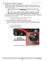
Page 34: ...installing or making any connections to the unit The Model 4123 Series units accomodates two different ways the customer can supply 100 240VAC power to the unit Depending on the connection configurati...

Page 35: ...ring clockwise While rotating the locking ring grooves in the ring will engage a set of pins on the outer casing of the male connector and pull both connectors together Continue turning the locking ri...

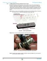
Page 36: ...lace and provides a tight seal where the cable penetrates the glandplate This seal provides for the safe operation of the unit in the hazardous locations for which it has been rated Step 1 Remove sixt...

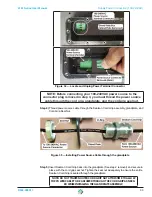
Page 37: ...rce cable through the Sealcon Cord Grip assembly glandplate and Cord Grip Seal Nut Figure 35 Installing Power Source Cable through the glandplate Step 5 Insert Sealcon Cord Grip back into the glandpla...

Page 38: ...in place with sixteen 16 glandplate hold down screws 6 32 Stainless Steel Pan Head Torx Screws 3 8 L See step 1 removal NOTE Carefully pull power cable through the cord grip while installing the gland...

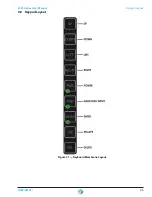
Page 39: ...4123 Series User Manual Keypad Layout D004 000017 35 9 0 Keypad Layout Figure 37 Keyboard Membrane Layout...

Page 40: ...about three hours to charge Storage Though the battery is embedded in a weather resistant enclosure and the 4123 storage temperature is 20 C to 55 C it is recommended that the battery not be subjected...

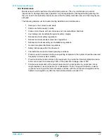
Page 41: ...s National and local accident prevention regulations National and local assembly and installation regulations General recognized technical regulations Safety instructions within this document Characte...

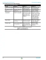
Page 42: ...ED s on the touch screen controller are lit Verify the driver for the touch screen loaded for the correct COM port Reset the computer using the internal reset switch Note accessing the reset switch mu...

Page 43: ...4123 Series User Manual D004 000017 July 2018 14 0 Revisions Revision Description Date Author Initial Release 7 20 2018 BM...

Reviews: