Installation Guide
Daintree
®
Networked Sensor Adapter (WSA10)
5
3
4
5
Mounting
Important Notices
Joining the Zigbee Network
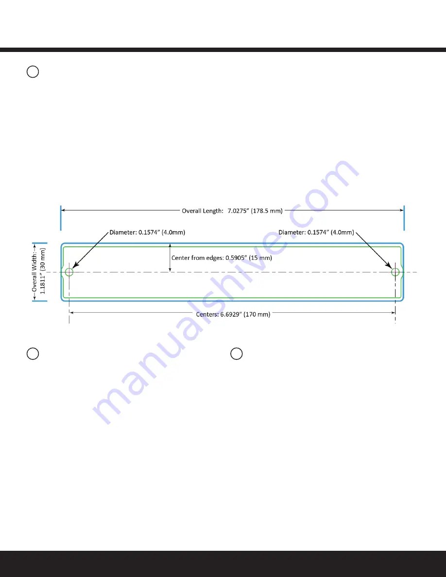
The WSA10 is designed to be mounted to a flat surface using
two screws. Alternatively, the mounting tabs at the end of the
WSA10 enclosure can be snapped off with pliers to make the
unit length up to 0.63” (3/4” or 16mm) smaller to fit into tighter
spaces. The grooves on the mounting tabs mark the snap-off
point, approximately 3/8” (8mm) from each end of the unit.
Note that when the tabs are removed the mounting holes are
lost, so the unit has to be mounted or affixed by other means,
such as permanent double-sided adhesive tape.
Record IEEE Addresses
If you have not already done so, be sure that each WSA10’s
IEEE address (last 4 or 5 digits) is recorded on the facility floor
plan. You can use the 4 or 5 digit Plan label supplied with the
WSA10 or you can write the last 4 or 5 digits on the floor plan.
This information will be used during the commissioning process.
After the system installation is complete, a marked-up copy of the
facility floor plan showing the identity and location of each wireless
adapter (including associated sensors) should be available. This
will simplify and expedite the commissioning process.
After the WSA10 is powered-up, it is ready to communicate
with the Daintree Wireless Area Controller (WAC) and the
ControlScope web-based user interface. Upon commissioning,
the WSA10 “Join” LED turns on solid and remains on as long as
the WSA10 is included in the ZigBee Network.
After joining the network, signals from the low voltage devices
connected to the WSA10 pass through the WSA10 and are sent
wirelessly to Daintree Networked. For more information about
configuring the system, see the instructions and on-line help
provided with the Daintree ControlScope web application.
Figure 8: Mounting Template (observe measurements,
illustration may not be actual size).for DC Power Supply


