


50
Centrifugal Chillers
IM 1044-2
Repair of System
Pressure Relief Valve Replacement
Current condenser designs use two relief valves separated by a three-way shutoff valve (one set). This three-way
valve allows either relief valve to be shut off, but at no time can both be shut off. In the event one of the relief
valves are leaking in the two valve set, these procedures must be followed:
•
If the valve closest to the valve stem is leaking, back seat the three-way valve all the way, closing the port to
the leaking pressure relief valve. Remove and replace the faulty relief valve. The three-way shutoff valve
must remain either fully back seated or fully forward to normal operation. If the relief valve farthest from the
valve stem is leaking, front seat the three-way valve and replace the relief valve as stated above.
•
The refrigerant must be pumped down into the condenser before the evaporator relief valve can be removed.
Pumping Down
If it becomes necessary to pump the system down, extreme care must be used to avoid damage to the evaporator
from freezing. Always make sure that full water flow is maintained through the chiller and condenser while
pumping down. To pump the system down, close all liquid line valves. With all liquid line valves closed and water
flowing, start the compressor. Set the MicroTech II control to the manual load. The vanes must be open while
pumping down to avoid a surge or other damaging condition. Pump the unit down until the MicroTech II
controller cuts out at approximately 20 psig. It is possible that the unit might experience a mild surge condition
prior to cutout. If this should occur, immediately shut off the compressor. Use a portable condensing unit to
complete the pump down, condense the refrigerant, and pump it into the condenser or pumpout vessel using
approved procedures.
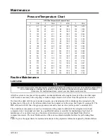
A pressure regulating valve must always be used on the drum being used to build the system pressure. Also, do not
exceed the test pressure given above. When the test pressure is reached disconnect the gas cylinder.
Pressure Testing
No pressure testing is necessary unless some damage was incurred during shipment. Damage can be determined
upon a visual inspection of the exterior piping, checking that no breakage occurred or fittings loosened. Service
gauges should show a positive pressure. If no pressure is evident on the gauges, a leak may have occurred,
discharging the entire refrigerant charge. In this case, the unit must be leak tested to determine the location of the
leak.
Leak Testing
In the case of loss of the entire refrigerant charge, the unit must be checked for leaks prior to charging the
complete system. This can be done by charging enough refrigerant into the system to build the pressure up to
approximately 10 psig (69 kPa) and adding sufficient dry nitrogen to bring the pressure up to a maximum of 125
psig (860 kPa). Leak test with an electronic leak detector. Halide leak detectors do not function with R-134a.
Water flow through the vessels must be maintained anytime refrigerant is added or removed from the system.
WARNING
Do not use oxygen or a mixture of R-22 and air to build up pressure as an explosion can occur causing
serious personal injury.
If any leaks are found in welded or brazed joints, or it is necessary to replace a gasket, relieve the test pressure in
the system before proceeding. Brazing is required for copper joints.
After making any necessary repair, the system must be evacuated as described in the following section.
Evacuation
After it has been determined that there are no refrigerant leaks, the system must be evacuated using a vacuum
pump with a capacity that will reduce the vacuum to
at least 1000 microns of mercury
.
A mercury manometer, or an electronic or other type of micron gauge, must be connected at the farthest point
from the vacuum pump. For readings below 1000 microns, an electronic or other micron gauge must be used.
The triple evacuation method is recommended and is particularly helpful if the vacuum pump is unable to obtain
the desired 1 millimeter of vacuum. The system is first evacuated to approximately 29 inches of mercury. Dry
nitrogen is then added to the system to bring the pressure up to zero pounds.


