


IM 1044-2
Centrifugal Chillers
3
Introduction
General Description
Daikin
Centrifugal Water Chillers are complete, self-contained, automatically controlled fluid chilling units.
Each unit is completely assembled and factory tested before shipment. Models WSC/WDC/WCC are cooling-
only and Models HSC are cooling with heat recovery accomplished in a bundle of condenser tubes separate
from the cooling tower tube bundle.
In the WSC and HSC series, each unit has one compressor connected to a condenser and evaporator. The WDC
series is equipped with two compressors operating in parallel on a single evaporator and condenser. The WCC
series is equipped with two compressors, each operating on one refrigerant circuit of a two circuit evaporator and
condenser. Information in this manual referring to WSC and WDC also applies to WCC and HSC units except
where specifically noted.
The chillers use refrigerant R-134a to reduce the size and weight of the package compared to negative pressure
refrigerants, and since R-134a operates at a positive pressure over the entire operation range, no purge system is
required. The controls are pre-wired, adjusted and tested. Only normal field connections such as piping, electrical
and interlocks, etc. are required, thereby simplifying installation and increasing reliability. Most necessary
equipment protection and operating controls are factory installed in the control panel.
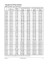
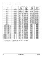
The basic sizes of units are the 063, 076, 079, 087, 100, 113 and 126. They provide a cooling capacity range from
200 to 2700 tons. In this manual all references to the WSC models will equally apply to other models unless
specifically referenced otherwise.
High Voltage Models
Certain 100, 113, and 126 size WDC and WCC units are available in high-voltage (10/11kV). These models will
have different dimensions, weights, and installation details than the standard low/medium voltage models. See
your Certified Dimension Drawing for details specific to your unit. See page 25 for the procedure to mount the
terminal box on 10/11 kV units.
Application
The procedures presented in this manual apply to the standard WSC/WDC/WCC family of chillers and HSC
heat recovery chillers. Refer to the Operating Manual, OM CentrifMicro-II for details of operation of the
MicroTech II
unit controller (latest version available on
www.DaikinApplied.com
).
All
Daikin
centrifugal chillers are factory tested prior to shipment and must be initially started at the job site by
a factory trained
Daikin
service technician. Failure to follow this startup procedure can affect the equipment
warranty. The standard limited warranty on this equipment covers parts that prove defective in material or
workmanship. Specific details of this warranty can be found in the warranty statement furnished with the
equipment.
Cooling towers used with
Daikin
centrifugal chillers are normally selected for maximum condenser inlet water
temperatures between 75°F and 90°F (24°C and 32°C). Lower entering water temperatures are desirable from the
standpoint of energy reduction, but a minimum does exist. For recommendations on optimum entering water
temperature and cooling tower fan control, consult
Daikin
catalog
CAT 605
, Applications Section, available on
www.DaikinApplied.com
. Heat recovery models, HSC, basically operate the same as cooling-only units. The
heat recovery function is controlled externally to the chiller as explained later in this manual.
W D C 063
W =
W
ater-cooled
H =
H
eat Recovery
D =
D
ual Compressor
S =
S
ingle Compressor
C = Dual,
C
ounterflow
C
entrifugal Compressor
Chiller Model, Based on
Impeller Diameter


