background image

Startup and Shutdown Procedures

www.DaikinApplied.com 63 

IOM 1322-1 • WATER-COOLED SCROLL COMPRESSOR

Flow Switch Installation and Calibration

A thermal dispersion flow switch uses heat to determine 

flow and therefore must be calibrated during system startup. 

A thermal dispersion flow switch can be an acceptable 

replacement for paddle type flow switches and differential 

pressure switches but care must be taken regarding wiring. 

The thermal dispersion flow switch supplied by Daikin Applied, 

shown in 

Figure 27

, comes as a 2 part unit consisting of a flow 

switch and an adapter labeled E40242 by the supplier.

Figure 27: Thermal Dispersion Flow Switch and Adapter    

Mounting

Figure 28

 highlights the position of the electrical connector and 

indentation ‘mark’ on flow switch.

Figure 28: Flow Switch Details      

It is required that the flow switch be mounted such that the 

electrical connection and indentation ‘mark’ are oriented as 

recommended in 

Figure 29

. It is important that the flow switch 

be mounted so that the probe is sufficiently inserted into the 

fluid stream. It may not be mounted directly on top or directly 

on the bottom of a horizontal pipe.

If the flow sensor is to be mounted away from the unit, the 

sensor should be mounted on the wall of the 

outlet

 pipe of 

evaporator and condenser, or in a run of straight pipe that 

allows 5 to 10 pipe diameters prior to the sensor and 3 to 5 

pipe diameters of straight pipe after the sensor. Flow switch 

is placed in outlet pipe to reflect flow leaving the barrel. If 

installation on the inlet pipe is necessary, contact Chiller 

Technical Response at [email protected] to 

review the jobsite details.

NOTE:  DO NOT

 alter or relocate factory installed flow 

switches. If issues exist, contact Chiller Technical 

Response at [email protected].

Figure 29: Remote Mounting Guidelines for Flow Switch   

If needed, the adapter is threaded into the pipe using pipe 

sealant appropriate for the application. The flow sensor is 

mounted onto the adapter using silicone grease. Carefully 

apply lubricant to the inside threads and o-ring so temperature 

probe does not become coated with lubricant. Torque the 

adapter/sensor connection to 18.5 ft/lbs.

Wiring

Refer to wiring diagram in the unit control panel. 

Either AC or DC is used to power the flow switch. The unit 

controller’s digital input is a DC signal which is supplied 

through the switch output of the flow switch for flow indication. 

It is required that the AC and DC commons of power be 

separated. Contact Chiller Technical Response for alternate 

wiring scenarios. 

Flow Switch Setup

The flow switch comes from the factory set at a default velocity 

of 20 cm/s. This value is typically well below the minimum 

water flow specified for the unit’s evaporator and condenser so 

field adjustment is required for adequate low flow protection. 

“Table 26: Flow Volume Calculation” on page 64

 are the 

calculated gallons per minute (gpm) for Schedule 40 steel pipe 

for various fluid velocities from 20 cm/s to 300 cm/s. The flow 

switch has an overall range of adjustment from 3 cm/s to 300 

cm/s. 

Step 1: 

Adjust flow through the evaporator to the minimum 

desired operating gpm. Maintain this flow throughout the setup 

procedure.

Summary of Contents for WGZ030DW

Page 1: ...ion and Maintenance Manual Water Cooled Scroll Compressor Chillers WGZ030DW WGZ200DW Packaged Water Cooled Chillers 30 200 Tons 105 700 kW R 410A 50 60 Hz IOM 1322 1 Group Chiller Part Number IOM1322...

Page 2: ...iderations 8 Condenser Water Piping 10 Packaged Unit Refrigerant Piping 11 Relief Valve Piping 12 Water Pressure Drop 12 Dimensions and Weights Packaged Units 16 Isolator Information 21 Physical Data...

Page 3: ...artup Oil heaters energized at least 12 hours before startup Chiller components EXV Sensors Transducers installed and wired properly Wiring complies with National Electrical Code and local codes See N...

Page 4: ......

Page 5: ...trical charge builds when halo carbon refrigerant travels in a rubber hose A grounding strap must be used between the auxiliary refrigerant tank and the chiller s end sheet earth ground which will saf...

Page 6: ...is not the responsibility of Daikin Applied Refrigerant Charge Every model WGZ DW water chiller with water cooled condensers is shipped with a full refrigerant charge For shipment the charge is contai...

Page 7: ...oving always apply pressure to the base on the skids only and not to the piping or other components A long bar will help move the unit Avoid dropping the unit at the end of the roll If the unit must b...

Page 8: ...d insulation thickness for accessibility It is recommended that the field installed water piping to the chiller include Some means of maintaining adequate system water pressure e g expansion tank or r...

Page 9: ...hot metal is dipped into the water tank Then the load would increase drastically Since there are many other factors that can influence performance systems can successfully operate below these suggesti...

Page 10: ...temperature from 15 F 9 4 C to 60 F 16 C Leaving chilled fluid temperatures below 40 F 4 6 C result in suction temperatures at or below the freezing point of water and a glycol anti freeze solution i...

Page 11: ...rature cannot be maintained at a 60 F minimum or when pond lake or well water that can fall below 60 F 15 C is used as the condensing medium special discharge pressure control must be used A water rec...

Page 12: ...discharge pipe from the pressure relief valve should not be less than the size of the pressure relief outlet 5 8 in flare See Figure 8 for pipe size when combining low side relief on compressor sucti...

Page 13: ...Application Considerations www DaikinApplied com 13 IOM 1322 1 WATER COOLED SCROLL COMPRESSOR Figure 9 WGZ D Condenser Pressure Drop Curves...

Page 14: ...IOM 1322 1 WATER COOLED SCROLL COMPRESSOR 14 www DaikinApplied com Application Considerations Table 2 WGZ D Evaporator Pressure Drop Curves...

Page 15: ...Application Considerations www DaikinApplied com 15 IOM 1322 1 WATER COOLED SCROLL COMPRESSOR Table 3 WGZ D Condenser Pressure Drop Data Table 4 WGZ D Evaporator Pressure Drop Data...

Page 16: ...IOM 1322 1 WATER COOLED SCROLL COMPRESSOR 16 www DaikinApplied com Dimensions and Weights Packaged Units Figure 10 WGZ030DW 060DW Packaged Dimensions and Weights Packaged Units...

Page 17: ...Dimensions and Weights Packaged Units www DaikinApplied com 17 IOM 1322 1 WATER COOLED SCROLL COMPRESSOR Figure 11 WGZ070DW Packaged...

Page 18: ...IOM 1322 1 WATER COOLED SCROLL COMPRESSOR 18 www DaikinApplied com Dimensions and Weights Packaged Units Figure 12 WGZ080DW 130DW Packaged...

Page 19: ...Dimensions and Weights Packaged Units www DaikinApplied com 19 IOM 1322 1 WATER COOLED SCROLL COMPRESSOR Figure 13 WGZ150DW 200DW Packaged...

Page 20: ...ww DaikinApplied com Dimensions and Weights Packaged Units Figure 14 Lifting Locations WGZ030 060D Packaged Table 5 Lifting Weights WGZ030 060D Packaged Figure 15 Lifting Locations WGZ070 130D Package...

Page 21: ...ngs running under the main unit supports The unit should be set initially on shims or blocks at the listed spring free height When all piping wiring flushing charging etc is completed the springs are...

Page 22: ...00 ID 900 ID 900 ID 900 RP 3 RP 3 RP 3 RP 3 Green Green Green Green Gray Gray Gray Gray WGZ070DW ID 1350 ID 1350 ID 1350 ID 1350 RP 4 RP 4 RP 4 RP 4 Purple Purple Purple Purple Brown Brown Brown Brown...

Page 23: ...hysical Data Packaged Units www DaikinApplied com 23 IOM 1322 1 WATER COOLED SCROLL COMPRESSOR Table 10 Physical Data WGZ030D WGZ040D Table 11 Physical Data WGZ045D WGZ055D Physical Data Packaged Unit...

Page 24: ...IOM 1322 1 WATER COOLED SCROLL COMPRESSOR 24 www DaikinApplied com Physical Data Packaged Units Table 12 Physical Data WGZ060D WGZ070D Table 13 Physical Data WGZ080D WGZ090D...

Page 25: ...Physical Data Packaged Units www DaikinApplied com 25 IOM 1322 1 WATER COOLED SCROLL COMPRESSOR Table 14 Physical Data WGZ100D WGZ130D Table 15 Physical Data WGZ150D WGZ200D...

Page 26: ...ns and can only be used if the condenser leaving water temperature is 105 F or less Circuit Breakers The circuit breaker used in the High Short Circuit panel option may have a higher trip rating than...

Page 27: ...l Data www DaikinApplied com 27 IOM 1322 1 WATER COOLED SCROLL COMPRESSOR Figure 18 Field Wiring Diagram Packaged Units NOTE Points 904 910 908 and 909 are only provided if dual pump output option is...

Page 28: ...door Motor Protection Module The motor protection system consists of an external control module located on each compressor motor terminal box connected to a series of thermistors located in the motor...

Page 29: ...for troubleshooting In addition to displaying alarm diagnostics the MicroTech II chiller controller also provides the operator with a warning of pre alarm conditions Staging The four scroll or six com...

Page 30: ...ircuit 2 UT Unit n Refrig Dependent NOTE 1 If Water Cooled Y then Entering Condenser If Water Cooled N then Outside Ambient NOTE 2 Selection of R134a in unit set point screen will modify unit operatio...

Page 31: ...No Fault 16 Open 16 Motor Protection 2 R134a R410A C2 0 VAC Fault 24 VAC No Fault 17 Ice Mode Switch UT 0 VAC Normal 24 VAC Ice 18 Heat Mode Switch UT 0 VAC Normal 24 VAC Heat NOTE 1 Units with singl...

Page 32: ...roller Digital Outputs The following parameters are digital outputs from this controller Types C1 Refrigerant Circuit 1 C2 Refrigerant Circuit 2 UT Unit Description Type Output Off Output On 1 Evap Wa...

Page 33: ...can be adjusted to any value in the Range column The unit controller is also used for TGZ Templifier R 134a in HEAT mode see IOM 1319 on www DaikinApplied com for further information The PW password c...

Page 34: ...IOM 1322 1 WATER COOLED SCROLL COMPRESSOR 34 www DaikinApplied com Unit Controller NOTE Temperature sensor SO 5 is Condenser Entering water sensor when Water Cooled ON...

Page 35: ...en cleared Evaporator Flow Loss Alarm description Evaporator Flow Loss Trigger 1 Evaporator Pump State Run AND Evaporator Flow Digital Input No Flow for time Evap Flow Proof Set Point AND at least one...

Page 36: ...point or higher and the freeze time has not been exceeded the timer will reset Action Taken Rapid stop circuit Reset This alarm can be cleared manually via the keypad if the evaporator pressure is ab...

Page 37: ...s of compressor operation Action Taken Rapid stop circuit Reset This alarm can be cleared manually via the keypad EXB Comm Failure on CP1 Alarm description No EXB comm CP1 Trigger CP1 does not have co...

Page 38: ...nt and number of High Condenser Pressure Unload occurrences since the circuit has cycled off or since midnight See table below Failed Pumpdown Event description Pumpdown Fail Cir N Trigger Circuit sta...

Page 39: ...point is set equal to the current LWT set point IN cool mode this will be Evap LWT and in heat mode this will be Heat LWT Reset Type 4 20 mA The Active Leaving Water set point is adjusted by the 4 to...

Page 40: ...is calculated for each circuit using the following equation Suction superheat Suction Temperature Evaporator Saturated Temperature Pump Down Pressure The pressure to which a circuit will pump down is...

Page 41: ...rotect inputs are ignored during this time so as to avoid tripping a false alarm Ice Mode Start Delay An adjustable start to start ice delay timer will limit the frequency with which the chiller may s...

Page 42: ...the Unit to shutdown compressors on a loss of flow up to two times every twenty four hours before locking the unit out on a Evaporator Flow Loss Alarm If there are no compressors running when Evapora...

Page 43: ...hutdown The Alarm indicators are turned On and the Circuit Status for any circuit with running compressors becomes Off Ready the Unit Status becomes Auto Wait For Flow and the condenser water pump sta...

Page 44: ...n the Valve Control Range Min set point and the Valve Control Range Max set point A valve increment shall be computed once every 5 seconds according to the following equation Increment Error Error Gai...

Page 45: ...rmal as well allowing multiple compressor restart attempts before locking out the circuit Low Ambient Start Procedure A low OAT start is initiated if the condenser refrigerant saturated temperature is...

Page 46: ...gerant 2 Number of compressors 3 Condenser configuration 4 How many high pressure unload occurrences since the previous midnight See below for initial offset value and step increase for each additiona...

Page 47: ...the network limit value received from the BAS and is determined as shown in the following graph NOTE In order to allow all stages to run a signal of 100 0 is required Maximum LWT Rate The maximum rat...

Page 48: ...The output should be off at all other times including the delay time described below The hot gas bypass valve opening will be delayed for Hot Gas Bypass Time set point seconds the default is 30 secon...

Page 49: ...al setting UP Increment increases the value of the setting DOWN Decrement decreases the value of a setting These four edit functions are indicated by one character abbreviation on the right side of th...

Page 50: ...keys on the controller are used to navigate through the menus The keys are also used to change numerical set point values contained in certain menus Figure 25 Menu Matrix Selection can be made within...

Page 51: ...Enable OFF Unit Mode COOL Source KEYPAD Unit Enable settings can be OFF and ON as determined from the Unit Enable set point Unit Enable is an external signal or a keypad setting that keeps the unit of...

Page 52: ...ompressor can stage off normally not by an alarm Default is 30 sec It is recommended that these settings not be changed of Compressors 4 SET COMP SPs 3 Comp 1 Enable Comp 3 Enable of Compressors 6 SET...

Page 53: ...ettings below 60 F are not recommended Water cooled On SET TOWER SPs 3 StageDiff XX X F Stage Up Tmr XX min StageDn Tmr XX min StageDiff is the number of degrees below the Stage ON that will turn off...

Page 54: ...fied by the Valve VFD Control set point The controlled parameter shall be the condenser entering water temperature When the desired output signal varies from 0 to 100 the output voltage shall vary as...

Page 55: ...place is the shutoff of all compressors running when the LowEvPrStop setting is reached default is 58 psi Reducing these time intervals will increase detrimental compressor cycling It is recommended t...

Page 56: ...Details Units of Measure Parameters will be expressed in different units dependant on the protocol selected Parameter Type Modbus Units BACnet Units LONworks Units Temperature F X 10 F X 10 C X 100 P...

Page 57: ...Unit Controller Operation www DaikinApplied com 57 IOM 1322 1 WATER COOLED SCROLL COMPRESSOR...

Page 58: ...0 to 59 Network Defaults The network set point default values are used only for the LONworks protocol Digital index 10 determines whether the network defaults should be loaded at startup The startup p...

Page 59: ...t command will be required for the lockout to be cleared Code 2 Open Shorted Motor Thermistor The module will flash the red Alert LED two times indicating the motor PTC thermistor circuit has a resist...

Page 60: ...If the relay does not close perform the following tests 1 1 Check the voltages between L1 L2 L1 L3 and L2 L3 These voltages should be approximately equal and within 10 of the rated three phase line to...

Page 61: ...hours before starting the unit 8 Check compressor oil level Prior to start up the oil level should cover at least one third of the oil sight glass located in the equalizing line between the compresso...

Page 62: ...s Do not leave the vessels or piping open to the atmosphere over the shutdown period Start up after Extended Shutdown 1 Inspect all equipment to see that it is in satisfactory operating condition 2 Re...

Page 63: ...rel If installation on the inlet pipe is necessary contact Chiller Technical Response at TechResponse DaikinApplied com to review the jobsite details NOTE DO NOT alter or relocate factory installed fl...

Page 64: ...tomatic Teach of Set point Table 26 Flow Volume Calculation Step 3 After the Teach function is completed and the outer LEDs flashed the flow switch will indicate a new set point based upon the current...

Page 65: ...ure is performed to toggle to unlocked NOTE 18 The LED window display on flow switch represents a velocity range of 50 cm s The window centers on the set point SP For example if the SP was set to 200...

Page 66: ...out additional compressors will stage off The last compressor will stage off when the LWT falls below the LWT Set point minus the Dead Band minus the Stop Delta T The stop Delta T is in effect for on...

Page 67: ...the compressors on a circuit are disabled then the circuit will be disabled If both circuits have all of their compressors disabled then the Unit State will remain Off Automatic Pump Down WGZ units ar...

Page 68: ...ath can occur The panel is always energized to ground even when the system switch is off To de energize the complete panel including crankcase heaters pull the main unit disconnect Be sure to read and...

Page 69: ...not running Phase Voltage Monitor Optional The phase voltage monitor is a device that provides protection against three phase electrical motor loss due to power failure conditions phase loss under ov...

Page 70: ...be slipped off its mounting stud for replacement Be sure to replace the coil on its mounting stud before returning the pumpdown switch to the auto pumpdown position To replace the entire solenoid valv...

Page 71: ...Unit Maintenance www DaikinApplied com 71 IOM 1322 1 WATER COOLED SCROLL COMPRESSOR...

Page 72: ...IOM 1322 1 WATER COOLED SCROLL COMPRESSOR 72 www DaikinApplied com Troubleshooting Chart Troubleshooting Chart...

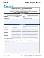
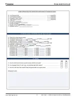
Page 73: ...Warranty Registration Form Scroll www DaikinApplied com 73 IOM 1322 1 WATER COOLED SCROLL COMPRESSOR Warranty Registration Form Scroll...

Page 74: ...IOM 1322 1 WATER COOLED SCROLL COMPRESSOR 74 www DaikinApplied com Troubleshooting Chart...

Page 75: ...Troubleshooting Chart www DaikinApplied com 75 IOM 1322 1 WATER COOLED SCROLL COMPRESSOR...

Page 76: ...IOM 1322 1 WATER COOLED SCROLL COMPRESSOR 76 www DaikinApplied com Troubleshooting Chart...

Page 77: ...Troubleshooting Chart www DaikinApplied com 77 IOM 1322 1 WATER COOLED SCROLL COMPRESSOR...

Page 78: ...IOM 1322 1 WATER COOLED SCROLL COMPRESSOR 78 www DaikinApplied com Troubleshooting Chart...

Page 79: ...Limited Product Warranty www DaikinApplied com 79 IOM 1322 1 WATER COOLED SCROLL COMPRESSOR Limited Product Warranty...

Page 80: ...uant to its standard terms and conditions of sale including Limited Product Warranty Consult your local Daikin Applied Representative for warranty details To find your local Daikin Applied Representat...

Reviews: