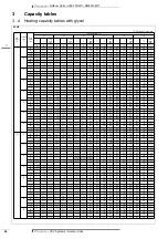


• Outdoor Units • HEAT PUMP • RWEYQ-MY1
1
6
• VRV Systems • Outdoor Units
74
6
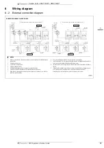
Wiring diagram
6 - 1
Wiring diagram
RWEYQ10MY1
3D048121
Power supply
Cool/Heat selector
In-Out
(note 2)
ON
OFF
Out-Out Out-Multi
Fan
Cool
Cool
Heat
Heat
Detail of M1C
El. Compo. Box
Operation ouput
Note 7
Is connector color for printed circuit board.
Is connector color for component.
Is discrimination color for component lead wire.
Cool/Heat selector (optional accessory)
Interlock
note 6
note 3
outdoor (Q1) (Q2)
outdoor (F1) (F2)
indoor (F1) (F2)
NOTES
1
This wiring diagram applies only to the outdoor unit.
2
When using the option adaptor, refer to the installation manual.
3
Refer to the installation manual, for connection wiring to indoor-outdoor transmission F1•F2,
outdoor-outdoor transmission F1•F2, outdoor-multi transmission Q1•Q2.
4
Refer to “service precatuion“ label (on el. compo. box cover), how to use BS1~BS5 and DS1 switch.
5
When operating, don’t short circuit for protection device. (S1PH)
6
Be sure to connect an interlock circuit between the terminal (3)-(4) of terminal strip (X3M).
7
Install a heat source water pump operation circtuit between the terminal (1)-(2) of terminal strip (X2M),
when interlock a heat source water pump and system operation.
8
Cool/Heat selector cannot be connected when operating heat recovery system.
L1-RED
L2-WHT
L3-BLK
N-BLUE
A1P
Printed circuit board (Main)
K9R
Magnetic relay (Y2S) (A1P)
V1CP
Safety devices input
A2P
Printed circuit board (Inv)
K10R
Magnetic relay (Operation output) (A1P)
V1R,V2R
Power module (A2P)
A3P
Printed circuit board (Noise filter)
K11R
Magnetic relay (Y5S) (A1P)
X1A,X3A
Connector (Y1E,Y3E)
BS1 ~ BS5
Push button switch
K12R
Magnetic relay (Y7S) (A1P)
X1M
Terminal strip (Power supply)
(Mode, Set, Return, Test, Reset)
K13R
Magnetic relay (E1HC) (A1P)
X1M
Terminal strip (Control) (A1P)
C63,66
Capacitor
L1R
Reactor
X2M
Terminal strip (A1P)
DS1
Dip switch
M1C
Motor (Compressor)
X3M
Terminal strip (Interlock)
E1HC
Crankcase heater
M1F,M2F
Motor (Fan, Inverter cooling))
X4M
Terminal strip (M1C)
F1U
Fuse (250V, 5A,
) (A3P)
PS
Switching power supply
Y1E
Electronic expansion valve (Main)
F1U, 2U
Fuse (250V, 10A,
) (A1P)
Q1RP
Phase reversal detect circuit (A1P)
Y3E
Electronic expansion valve (Sub cool)
F3U
Fuse (250V, 5A,
)
R50,R59
Resistor
Y1S
Solenoid valve (Hot gas bypass)
H1P ~ H8P
Pilot lamp (Service monitor-orange) (A1P)
R95
Resistor (Current limiting)
Y2S
Solenoid valve (Oil recovery)
[H2P] Prepare, test ...................... flickering
R1T
Thermistor (Fin) (A2P)
Y3S
Solenoid valve (Receiver pressurization)
Malfuntion detection .... light up
R2T
Thermistor (Suction)
Y4S
Solenoid valve (Receiver gas purge)
HAP
Pilot lamp (Service monitor-green) (A1P)
R3T
Thermistor (M1C Discharge)
Y5S
Solenoid valve (4 way valve) (Main)
K1
Magnetic relay
R4T
Thermistor (Heat exchanger gas pipe)
Y6S
Solenoid valve (Liquid pipe)
K2
Magnetic contactor (M1C)
R5T
Thermistor (Sub cooling heat exchanger)
Y7S
Solenoid valve (4 way valve) (Heat exchanger)
K3R
Magnetic relay (Y1S) (A1P)
R6T
Thermistor (Receiver liquid pipe)
Z1C
Noise filter (Ferrite core)
K5R
Magnetic relay (Y3S) (A1P)
S1NPH
Pressure sensor (High)
Z1F
Noise filter (With surge absorber)
K6R
Magnetic relay (Y4S) (A1P)
S1NPL
Pressure sensor (Low)
Cool/heat selector
K7R
Magnetic relay (M1F,M2F) (A1P)
S1PH
Pressure switch (High)
S1S
Selector switch (Fan/Cool • Heat)
K8R
Magnetic relay (Y6S) (A1P)
T1R
Transformer (220-240V/20V)
S2S
Selector switch (Cool/Heat)
: Field wiring
COLORS : BLK : Black
RED : Red
WHT : White
BLU : Blue
ORG : Orange
PNK : Pink
GRY : Grey
: Connector
: Terminal
: Terminal strip
: Protective earth (screw)


