


RXYSQ4~ RXYSQ4~6P7Y1B
VRVIII-S system air conditioner
4PW35338-1
Installation manual
6
7.1.
Selection of piping material
■
Foreign materials inside pipes (including oils for fabrication)
must be
≤
30 mg/10 m.
■
Construction material: phosphoric acid deoxidized seamless
copper for refrigerant.
■
Temper grade: use piping with temper grade in function of the
pipe diameter as listed in table below.
■
The pipe thickness of the refrigerant piping should comply with
relevant local and national regulations. The minimal pipe
thickness for R410A piping must be in accordance with the table
below.
O = Annealed
1/2H = Half hard
■
Make sure to use the particular branches of piping that have
been selected.
■
In case the required pipe sizes (inch sizes) are not available, it is
also allowed to use other diameters (mm sizes), taken the
following into account:
■
select the pipe size nearest to the required size.
■
use the suitable adapters for the change-over from inch to
mm pipes (field supply).
8.
P
RECAUTIONS
ON
REFRIGERANT
PIPING
■
Do not allow anything other than the designated refrigerant to
get mixed into the freezing cycle, such as air, etc. If any
refrigerant gas leaks while working on the unit, ventilate the
room thoroughly right away.
■
Use R410A only when adding refrigerant
Installation tools:
Make sure to use installation tools (gauge manifold charge hose,
etc.) that are exclusively used for R410A installations to withstand
the pressure and to prevent foreign materials (e.g. mineral oils
and moisture) from mixing into the system.
Vacuum pump:
Use a 2-stage vacuum pump with a non-return valve
Make sure the pump oil does not flow oppositely into the system
while the pump is not working.
Use a vacuum pump which can evacuate to –100.7 kPa (5 Torr,
–755 mm Hg).
■
In order to prevent dirt, liquid or dust from entering the piping,
cure the piping with a pinch or taping.
Great caution is needed when passing copper tubes through
walls.
■
For handling of stop valves, refer to
.
■
Only use the flare nuts included with the unit. Using different
flare nuts may cause the refrigerant to leak.
■
Always use the supplied copper gasket when connecting the
gas pipe supplied with the unit. See
8.1.
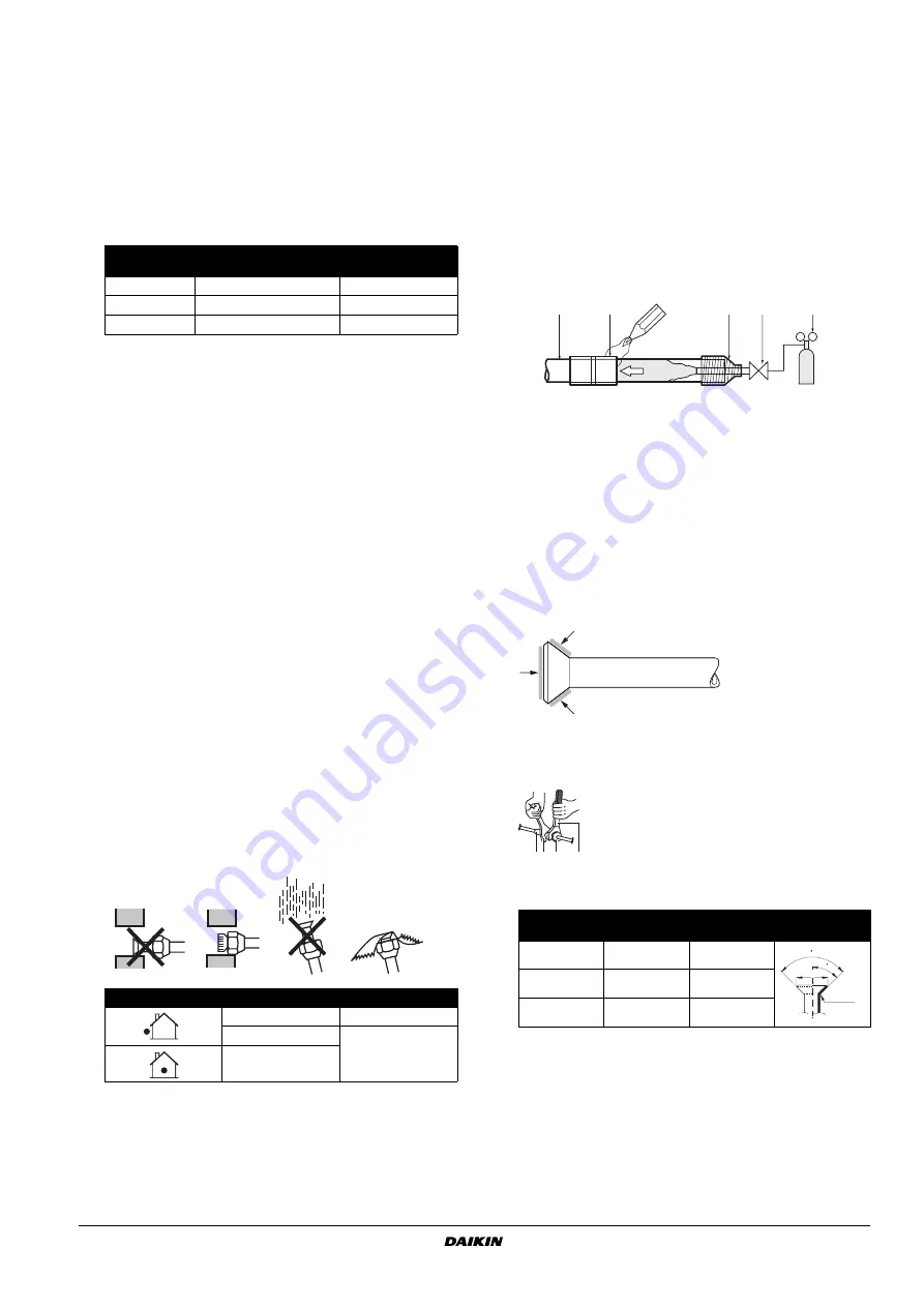
Cautions for brazing
■
Be sure to carry out a nitrogen blow when brazing.
Brazing without carrying out nitrogen replacement or releasing
nitrogen into the piping will create large quantities of oxidized
film on the inside of the pipes, adversely affecting valves and
compressors in the refrigerating system and preventing normal
operation.
■
When brazing while inserting nitrogen into the piping, nitrogen
must be set to 0.02 MPa with a pressure-reducing valve (=just
enough so that it can be felt on the skin).
8.2.
Cautions for flare connection
■
See the following table for flare part machining dimensions.
■
When connecting the flare nuts, apply refrigerant ether or ester
oil to the inside and outside of the flares and turn them three or
four times at first.
■
When loosening a flare nut, always use two wrenches in
combination. When connecting the piping, always use a spanner
and torque wrench in combination to tighten the flare nut.
■
See the following table for tightening torque.
(Applying too much torque may cause the flares to crack.)
■
After all the piping has been connected, use nitrogen to perform
a gas leak check.
Pipe Ø
Temper grade of piping
material
Minimal thickness t
(mm)
6.4 / 9.5 / 12.7
O
0.80
15.9
O
1
19.1
1/2H
1
Installation period
Protection method
More than a month
Pinch the pipe
Less than a month
Pinch or tape the
pipe
Regardless of the
period
1
Refrigerant piping
2
Part to be brazed
3
Taping
4
Hands valve
5
Pressure-reducing valve
6
Nitrogen
Pipe size
Tightening
torque (N•m)
A (mm)
Flare shape
Ø9.5
32.7~39.9
12.8~13.2
Ø15.9
61.8~75.4
19.3~19.7
Ø19.1
97.2~118.6
12.3~23.7
1
2
3
4
5
6
6
12 3
4
1
Piping union
2
Spanner
3
Flare nut
4
Torque wrench
R=0.4~0.8
45
±
2
90
±
2
A


