background image

IM 777-8 • Skyline Air Handler 34 www.DaikinApplied.com

s

ervICe


and

 M

aInTenanCe


VM and VP Variable Pitch Key Type 

Sheaves 

Mounting 

1.  Mount all sheaves on the motor or driving shaft with the 

setscrews 

A

 toward the motor. 

2.  Verify that both driving and driven sheaves are in 

alignment and that shafts are parallel. 

3.  Fit internal key 

D

 between sheave and shaft and lock 

setscrew 

A

 securely in place. 

Adjusting 

1.  Loosen setscrews 

B

 and 

C

 in moving parts of sheave 

and pull out external key 

E

. (This key projects a small 

amount to provide a grip for removing.) 

2.  To adjust sheave pitch diameter for desired speed, open 

moving parts by half or full turns from closed position. 

Do 

not open more than five full turns for 

A

 belts or six 

full turns for 

B

 belts

3.  Replace external key 

E

 and securely tighten setscrews 

B


over key and setscrews 

C

 into keyway in fixed half of the 

sheave. 

4.  Put on belts and adjust belt tension. 

Do not force belts 

over grooves .

 See 

See Fan Drive Belt Adjustment on 

page 37

5.  Make future adjustments by loosening the belt tension 

and increasing or decreasing the pitch diameter of the 

sheave by half or full turns as required. Re-adjust belt 

tension before starting drive. 

6.  To provide the same pitch diameter, adjust both halves 

of the two-groove sheaves by the same number of turns 

from closed position. 

7.  Verify that all keys are in place and that all setscrews 

are tight before starting drive. Check setscrews and belt 

tension after 24 hours service. 

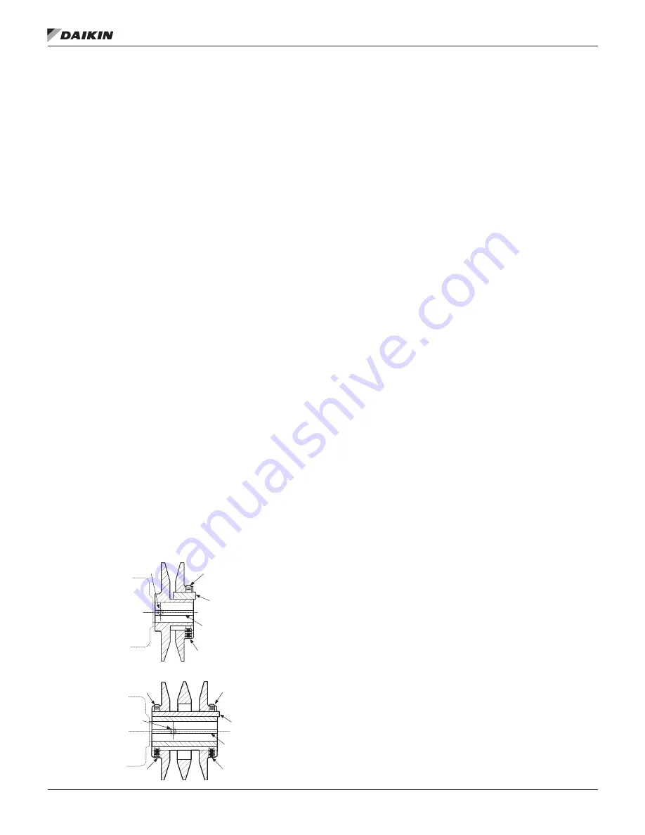
Figure 47: VP Type Sheave Adjustment     

LVP Variable Speed Sheaves 

Mounting 

1.  Slide sheave on motor shaft so that the side of the 

sheave with setscrew 

A

 is next to the motor when 

setscrew 

A

 is in the hub or barrel of the sheave. 

2.  When setscrew 

A

 is at an angle in the center flange 

B

mount it away from the motor so that the outer locking 

ring and flange can be removed to get to the setscrew. 

3. 

To remove the flange and locking ring: 

a.  Loosen setscrews 

D

b.  Loosen but 

do not remove

 capscrews 

E

c.  Remove key 

F

d. 

Rotate the flange counterclockwise until it 

disengages the threads on the sheave barrel. 

NOTE: 

This key projects a small amount to provide a grip for 

removing. 

4.  Verify that the driving and driven sheaves are in 

alignment and the shafts are parallel. When aligning two-

groove sheaves, allow room between the sheave and 

motor to access capscrews 

E

5.  Insert key 

C

 between the sheave and the shaft and 

tighten setscrew 

A

 securely. 

6. 

If flange and locking ring have been removed, when 

replacing them make sure that the inner and outer 

flanges are open from the closed position by the same 

amount as the other flange. Determine this by accurately 

measuring the top width of the grooves. 

7.  Insert key 

F

8.  Tighten setscrews 

D

 and capscrews 

E

9.  Put on belts and adjust belt tension. 

Do not force belts 

over grooves .

 See 

See Fan Drive Belt Adjustment on 

page 37

10.  Before starting the drive, ensure that all keys are in 

place and all setscrews and all capscrews are tight. 

Check and retighten all screws and retention belts after 

approximately 24 hours of service. 

Two Groove

C

A

B

B

D

E

C

A

D

E

D

C

Single Groove

Key "E" projects

to provide a grip

for removal.

Do not operate

sheeves with flange

projecting beyond

the hub end.

Summary of Contents for Skyline IM 777-8

Page 1: ...Installation and Maintenance Manual IM 777 8 Group Applied Air Systems Part Number IM 777 Date March 2014 Skyline Outdoor Air Handler...

Page 2: ...s 14 Internal Isolation Assembly Adjustment 18 OSHPD Seismic Anchoring Mounting 20 Electrical Installation 21 Wiring 21 Operation Guidelines 22 Startup Checks 22 Before Starting the Unit 22 VFD Setup...

Page 3: ...el and are inspected thoroughly before leaving the factory Take care during installation to prevent damage to units 3 Take special care when handling the blower section All fans are dynamically balanc...

Page 4: ...on galvanized surfaces Belt driven fans Reduce belt tension by at least 50 or remove the belts Remove belts if they will be subjected to temperatures exceeding 85 F to avoid deterioration Remove belt...

Page 5: ...supplied with VFDs Figure 1 Servicing Space Requirements Figure 2 Service Clearance for Electrical Power Devices Rigging Skyline air handlers ship as separate sections completely assembled or in modu...

Page 6: ...nt attached on the leaving air side of the shipping section that seals against the frame channel on the entering air side of the adjoining The splice joint is insulated and provides an air tight seal...

Page 7: ...ping screw to secure the bases together f For certain Custom Air Handling units use the provided section joining plates to fasten sections together Space them as shown in Figure 9 Using the provided 1...

Page 8: ...he flat head Torx 30 fasteners in the corner of the frame channels Then pull the frame channel out the side Remove any panel screws that are within one inch of the of the frame since they are engaged...

Page 9: ...available inside the unit for conduit or pipe routing b Do not locate holes in a panel that provides access to key maintenance components such as filters and fan assemblies c Do not locate where the c...

Page 10: ...and does not interfere with other vital components Duct Connections Use flexible connectors on the outlet and inlet duct connections of all units Do not position down flow fans over air ducts that ar...

Page 11: ...shaft torque is 205 inches pound Greater rotation or torque can cause equipment damage Face and Bypass Section Mounting Internal and external face and bypass sections are mounted together using the i...

Page 12: ...ls WARNING Use all lifting points Improper lifting can cause severe personal injury and property damage CAUTION Lifting points may not be symmetrical to the center of gravity of the unit Ballast or un...

Page 13: ...M 777 8 Skyline Air Handler Figure 22 Typical Vestibule Figure 23 Caulking the Vestibule Roof Cap Figure 24 Detail of Mounting Screws Figure 25 Additional Caulking SHOWN SPLICE COLLAR DETAIL A UNIT TO...

Page 14: ...ply heat to the body of the expansion valve The thermostatic expansion valve must be the external equalizer tube type Connect the 1 4 inch diameter external equalizer tube provided on the coil to the...

Page 15: ...low Valves Do not use modulating steam valves on high pressure systems Properly size modulating valves Do not undersize Avoid freezing conditions entering air temperatures below 35 F Daikin strongly r...

Page 16: ...Pressure to 25 psi 5GA or 8GA coils Note that the addition of a vacuum breaker to permit the coil to drain during shutdown 5TA 8TA or 5HA coils Conden sate is lifted to overhead return main 5JA or 8J...

Page 17: ...o be heated by a hot water coil carefully design the system to provide thorough mixing before air enters the coil To prepare coils for winter operation See Winterizing Water Coils on page 39 Drain Pan...

Page 18: ...orz H Downblast H Upblast H Unit Sizes 003 035 1 3 75 3 75 4 25 2 4 25 3 75 4 25 3 4 25 3 75 4 25 4 3 75 3 75 4 25 Unit Sizes 040 090 1 6 00 6 75 6 75 2 6 50 6 75 6 75 3 6 50 6 75 6 75 4 6 00 6 75 6 7...

Page 19: ...Air Handler Figure 30 Removing Motor Behind Shipping Brackets Figure 31 Removing Motor Beside Shipping Brackets Figure 32 Plenum Fan Typical Shipping Brackets Shipping hold down nut and bolt Remove a...

Page 20: ...e are to be field drilled Any mounting hardware is to be field supplied Table 6 OSHPD Mounting Attachment Method SDS Attachment System by Others Spacing System Bolted attachment to steel Figure 33 1 9...

Page 21: ...self will be mounted on the drive side fan panel inside the fan cabinet The external junction box will provide loose wire connection to the VFD and to the motor An external mounted keypad display cont...

Page 22: ...quipment damage due to loose fasteners represents improper start up and equipment abuse It is not covered by the warranty 1 Check that the unit is completely and properly installed with ductwork conne...

Page 23: ...Hours of Operation 1 Disconnect and lock electrical power source 2 Check tightness of all bearing wheel and sheave setscrews or capscrews See Table 14 on page 26 3 Recheck belt tension and adjust if n...

Page 24: ...Funnel Relationship 13 to 36 Belt Drive Plenum Fan Wheel Funnel Parameters in mm Size in A B C 13 0 25 6 35 0 91 23 11 3 50 88 9 15 0 25 6 35 0 91 23 11 3 50 88 9 16 0 25 6 35 0 91 23 11 3 50 88 9 18...

Page 25: ...12 Wheel to Inlet Funnel Relationship Direct Drive Class II fans Fan Size in Overlap in mm 11 0 25 6 35 12 0 25 6 35 15 0 25 6 35 16 0 38 9 65 18 0 38 9 65 20 0 41 10 41 22 0 45 11 43 24 0 50 12 7 27...

Page 26: ...II Plenum Fans Only Fan Size Setscrew Size Torque ft lb Aluminum Steel 11 12 13 3 8 19 2 N A 15 3 8 19 2 N A 16 3 8 19 2 N A 18 3 8 19 2 N A 20 3 8 19 2 N A 22 3 8 19 2 N A 24 3 8 19 2 N A 27 3 8 19 2...

Page 27: ...or is replaced After fan and or motor replacement the block off plate is to be removed and stored outside of the air tunnel The Daikin Fan Array has an optional gravity actuated block off damper These...

Page 28: ...can be simplified by assuming standard density and assuming funnel dimensions match the drawing dimensions Table 17 shows the factor F for each fan size and type The equation then becomes the followin...

Page 29: ...ecure tubing to the fan assembly using cable tie mount DCX52 and Cable tie DCX54 as needed Make sure any tubing does not interfere with the fan wheel NOTE Never drill or screw through the inlet funnel...

Page 30: ...rpm Class I 2077 1875 1691 1479 1328 1209 1073 Maximum rpm Class Il 2703 2413 2199 1928 1730 1579 1401 Table 20 Operating Limits Belt Drive Plenum Fans Fan Operating Limits Belt Drive Plenum Fans Size...

Page 31: ...tributes to premature fan and motor bearing failure Monitor overall vibration levels every six months of operation An increase in levels is an indication of potential trouble Vibration Causes 1 Wheel...

Page 32: ...Motor Bearings Mfr Grease NEMA Size Amount to Add oz Texaco Polystar or Polyrex EM Exxon Mobil or Rykon Premium 2 or Penzoil Pen 2 Lube 56 to 140 0 08 140 0 15 180 0 19 210 0 30 250 0 47 280 0 61 320...

Page 33: ...59 3 to 3 7 16 75 80 0 85 24 10 3 1 2 to 4 85 105 1 5 42 53 Fan Drive WARNING Before servicing lock out and tag out all power to the unit Fans or belts cause severe personal injury or death WARNING D...

Page 34: ...djustment LVP Variable Speed Sheaves Mounting 1 Slide sheave on motor shaft so that the side of the sheave with setscrew A is next to the motor when setscrew A is in the hub or barrel of the sheave 2...

Page 35: ...f the driven sheave See Figure 49 2 Verify that all setscrews are torqued to the values shown in Table 28 before starting drive Check setscrew torque and belt tension after 24 hours of service Adjusti...

Page 36: ...lbs Seating torque in lbs Seating torque in lbs Seating torque in lbs Seating torque in lbs Length L in lbs Seating torque in lbs 1 4 20NC 150 12 5 100 87 7 3 3 16 50 5 16 11NC 305 25 4 200 165 13 8 1...

Page 37: ...cause slippage 5 Inspect V drive on a periodic basis Adjust tension if the belt is slipping Do not apply belt dressing This can damage the belt and cause early failure Tension Measurement Procedure 1...

Page 38: ...gauge is used the prefilters can be removed to check the pressure drop of the final filters Figure 53 Filter Gauge Table 30 Filter Pressure Drops Bag filters DriPak 2000 Efficiency 45 65 85 95 Rated...

Page 39: ...o prevent freeze up NOTE Carefully read instructions for mixing antifreeze solution used Some products have a higher freezing point in their natural state when mixed with water Daikin is not responsib...

Page 40: ...iping and remove the brass plugs for the vents and drains located in the connections 2 Remove all screws and remove the access panel 3 Remove the screws holding the coil in place 4 Lift and pull the c...

Page 41: ...he coil is in place bolt the coil to the section 4 Caulk the mounting surface of the steel plate and install the plate on the coils 5 Caulk the mounting surface of the drain trough and install the dra...

Page 42: ...turn Material Procedure Defective material may not be returned without permission of authorized factory service personnel of Daikin in Minneapolis Minnesota 763 553 5330 A Return Goods tag must be inc...

Page 43: ...____________ RF VFD model number __________________________________________________ Serial number __________________________ Circle Yes or No If not applicable to the type of unit circle N A I INITIAL...

Page 44: ...3 ___________ ____________ ____________ ___________ ___________ ____________ G FLA L1 ___________ L2____________ L3 ___________ H Operate electric heat with fans off Electric heat must cycle on high l...

Page 45: ...______________________ 2 How would you rate the overall appearance of the product i e paint fin damage etc Excellent Good Fair Poor 3 Did all sections of the unit fit together properly Yes No N A 4 Di...

Page 46: ...ndard terms and conditions of sale including Limited Product Warranty Consult your local Daikin Applied representative for warranty details Refer to Form 933 430285Y To find your local Daikin Applied...

Reviews: