background image

AZQS7 AZQS100~14  AZQS100~140A7W1B
Split System air conditioners
4PW68422-1 – 03.2011

Installation manual

8

Cautions for necessity of a trap

Since there is fear of the oil held inside the riser piping flowing back into
the compressor when stopped and causing liquid compression
phenomenon, or cases of deterioration of oil return, it will be necessary
to provide a trap at an appropriate place in the riser gas piping.

Trap installation spacing. 

(See figure 3)

A

Outdoor unit

B

Indoor unit

C

Gas piping

D

Liquid piping

E

Oiltrap

H

Install trap at each difference in height of 10 m.

A trap is not necessary when the outdoor unit is installed in a
higher position than the indoor unit.

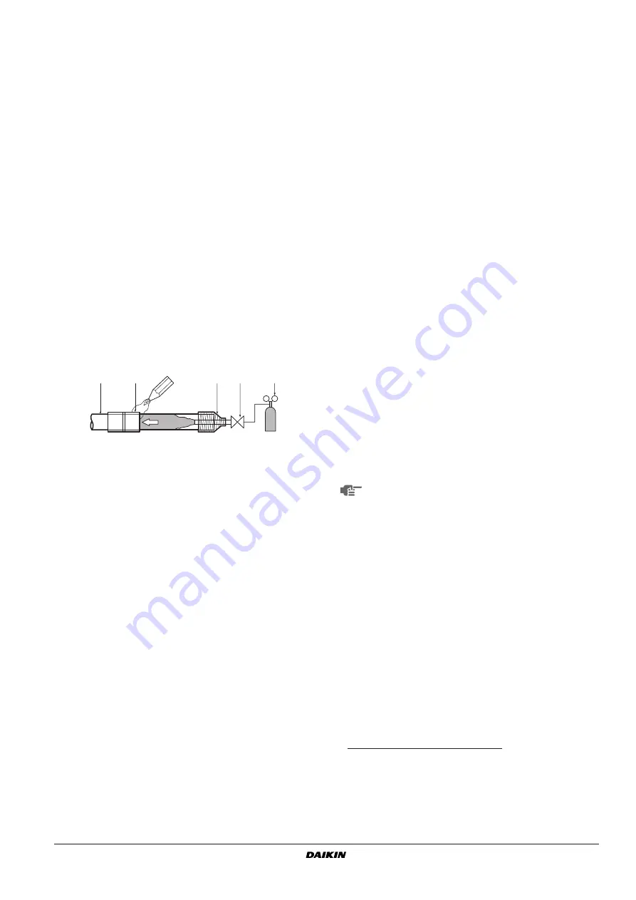
Cautions for brazing

Be sure to carry out a nitrogen blow when brazing.
Brazing without carrying out nitrogen replacement or releasing
nitrogen into the piping will create large quantities of oxidised
film on the inside of the pipes, adversely affecting valves and
compressors in the refrigerating system and preventing normal
operation. When brazing pipes however, do not use oxidation
preventers. Residue of such preventers may result in choking of
pipes or malfunction of components.

When brazing while inserting nitrogen into the piping, nitrogen
must be set to 0.02 MPa with a pressure-reducing valve (=just
enough so that it can be felt on the skin).

E

VACUATING

Do not purge the air with refrigerants. Use a vacuum pump to
vacuum the installation. No additional refrigerant is provided for
air purging.

Pipes inside the units were checked for leaks by the
manufacturer. The refrigerant pipes fit on site are to be checked
for leaks by the installer.

Confirm that the valves are firmly closed before leak test or
vacuuming.

Set up for vacuuming and leak test: 

see 

figure 5

Procedure for leak test

Leak test must satisfy EN378-2.

1

Evacuate the pipes and check vacuum

(1)

. (No pressure increase

for 1 minute.)

2

Break the vacuum with a minimum of 2 bar of nitrogen. (Never
pressurize more than 4.0 MPa.)

3

Conduct leak test by applying soap water, etc. to the connecting
part of the pipes.

4

Discharge nitrogen.

5

Evacuate and check vacuum again

(1)

.

6

If the vacuum gauge no longer rises, the stop valves can be
opened.

1

Refrigerant piping

2

Part to be brazed

3

Taping

4

Hands valve

5

Pressure-reducing valve

6

Nitrogen

1

2

3

4

5

6

6

1

Pressure gauge

2

Nitrogen

3

Refrigerant

4

Weighing machine

5

Vacuum pump

6

Stop valve

(1) Use a 2-stage vacuum pump with a non return valve which 

can evacuate to –100.7 kPa (5 Torr, –755 mm Hg).
Evacuate the system from the liquid and gas pipes by using 
a vacuum pump for more than 2 hours and bring the system 
to –100.7 kPa. After keeping the system under that condition 
for more than one hour, check if the vacuum gauge rises or 
not. If it rises, the system may either contain moisture inside 
or have leaks.

Following should be executed if there is a possibility of
moisture remaining in the pipe (if piping work is carried out
during the raining season or over a long period of time,
rainwater may enter the pipe during work).
After evacuating the system for 2 hours, pressurize the
system to 0.05 MPa (vacuum break) with nitrogen gas and
evacuate the system again using the vacuum pump for
1 hour to –100.7 kPa (vacuum drying). If the system
cannot be evacuated to –100.7 kPa within 2 hours, repeat
the operation of vacuum break and vacuum drying. Then
after leaving the system in vacuum for 1 hour, confirm that
the vacuum gauge does not rise.

After air purging with a vacuum pump it may happen that
the refrigerant pressure does not rise, not even if the stop
valve is opened. Reason for this phenomenon is the closed
state of for instance the expansion valve in the outdoor unit
circuit, but this is not a problem for running the unit.

Summary of Contents for Siesta AZQS100A7V1B

Page 1: ...INSTALLATION MANUAL AZQS71A2V1B AZQS100A7V1B AZQS125A7V1B AZQS140A7V1B AZQS100A7W1B AZQS125A7W1B AZQS140A7W1B Split System air conditioners ...

Page 2: ...50 Hz 220 240 V R410A 1 2 4 5 6 3 1 3 2 4 5 A B A E B C D H H1 L1 A A B2 B2 B2 C C D1 D1 D1 D2 D2 D2 D2 D2 E E H H L1 L1 L1 L2 L2 L2 A A B1 B1 B1 B1 B1 B1 B2 B2 B2 C C D1 D1 D1 D2 D2 D2 D2 D2 E E H H L1 L1 L1 L2 L2 L2 1 1 2 L1 L3 L2 L1 L3 L2 1 2 3 4 5 6 ...

Page 3: ...ıÂÙÈÎ fi ÙÔ B Û ÌÊˆÓ Ì ÙÔ ÈÛÙÔ ÔÈËÙÈÎfi C 08 Nota tal como estabelecido em A e com o parecer positivo de B de acordo com o Certificado C 09 Примечание как указано в A и в соответствии с положительным решением B согласно Свидетельству C 10 Bemærk som anført i A og positivt vurderet af B i henhold til Certifikat C 11 Information enligt A och godkänts av B enligt Certifikatet C 12 Merk som det fremkom...

Page 4: ...llation work may result in accidents due to fall of equipment Make certain that all electrical work is carried out by qualified personnel according to the local laws and regulations and this installation manual using a separate circuit Insufficient capacity of the power supply circuit or improper electrical construction may lead to electric shocks or fire Make sure that all wiring is secure using ...

Page 5: ...vels of salt such as that near the ocean Where voltage fluctuates a lot such as that in factories In vehicles or vessels Where acidic or alkaline vapour is present Provide a logbook In accordance with the relevant national and international codes it may be necessary to provide a logbook with the equipment containing at least info on maintenance repair work results of tests stand by periodes etc In...

Page 6: ...strong wind blows continuously on the face of the unit the fan can start rotating very fast until it breaks Refer to the figures for installation of this unit in a place where the wind direction can be foreseen Turn the air outlet side toward the building s wall fence or screen Set the outlet side at a right angle to the direction of the wind 3 Prepare a water drainage channel around the foundatio...

Page 7: ...ipe disposal from the outdoor unit causes trouble for example if the drain water may splash on people provide the drain piping using a drain socket optional Make sure the drain works properly INSTALLATION SERVICING SPACE The numerical figures used in here represent the dimensions for the 71 100 125 140 class models Figures between indicate the dimensions for the 100 125 140 class models Unit mm Re...

Page 8: ... L H 0 L 1 2H 150 250 1 2H L 200 300 H L Installation impossible Installation shall be done by a licensed refrigeration technician the choice of materials and installation shall comply with the applicable national and international codes In Europe EN378 is the applicable standard that shall be used To persons in charge of piping work Be sure to open the stop valve after piping installing and vacum...

Page 9: ...repair paint to the edge and the surrounding end surfaces to prevent rusting Preventing foreign objects from entering Plug the pipe through holes with putty or insulating material procured locally to stop up all gaps as shown in the figure Insects or small animals entering the outdoor unit may cause a short circuit in the electrical box Cautions for handling stop valve The stop valves for indoor o...

Page 10: ... material If the temperature is higher than 30 C and the humidity is higher than RH 80 then the thickness of the sealing materials should be at least 20 mm in order to avoid condensation on the surface of the sealing Be sure to insulate the liquid and gas side field piping and the refrigerant branch kit The highest temperature that the gas side piping can reach is around 120 C so be sure to use in...

Page 11: ...cedure for leak test Leak test must satisfy EN378 2 1 Evacuate the pipes and check vacuum 1 No pressure increase for 1 minute 2 Break the vacuum with a minimum of 2 bar of nitrogen Never pressurize more than 4 0 MPa 3 Conduct leak test by applying soap water etc to the connecting part of the pipes 4 Discharge nitrogen 5 Evacuate and check vacuum again 1 6 If the vacuum gauge no longer rises the st...

Page 12: ...s relate to the refrigerant piping length as in Maximum total one way piping length of the table in paragraph Allowable pipe length and height difference on page 5 Table 2 Total charging amount unit kg NOTE National implementation of EU regulation on certain fluorinated greenhouse gases may require to provide the appropriate official national language on the unit Therefore an additional multilingu...

Page 13: ...side Make sure no external pressure is applied to the terminal connectors When installing the earth leakage breaker make sure that it is compatible with the inverter resistant to high frequency electrical noise to avoid unnecessary opening of the earth leakage breaker As this unit is equipped with an inverter installing a phase advancing capacitor not only will deteriorate power factor improvement...

Page 14: ...easons be sure to observe the following instruction Do not connect wires of different gauge to the same power supply terminal Looseness in the connection may cause overheating When connecting wires of the same gauge connect them according to the below figure Use the correct screwdriver to tighten the terminal screws Small screwdrivers can damage the screw head and prevent appropriate tightening Ov...

Page 15: ...e unit returns to normal operation 10 Check all functions according to the operation manual AZQS 71V1 100V1 125V1 140V1 100W1 125W1 140W1 Minimum circuit amps MCA a a Stated values are maximum values see electrical data of combination with indoor units for exact values 18 9 27 6 28 8 17 1 18 3 Recommended field fuse A 20 32 20 Wire type b b Only in protected pipes use H07RN F when protected pipes ...

Page 16: ...may have run out If the remote controller shows E3 E4 or L8 as an error code there is a possibility that either the stop valves are closed or that air inlet or air outlet are blocked If the error code U2 is displayed on the remote controller check for voltage imbalance If the error code U4 or UF is displayed on the remote controller check the inter unit branch wiring connection If the error code L...

Page 17: ...or discharge for V1 models only R3T Thermistor discharge pipe for W1 models only R3T Thermistor suction pipe for V1 models only R4T Thermistor suction pipe for W1 models only R4T Thermistor coil for V1 models only R5T Thermistor power module for W1 models only R5T Thermistor coil middle for V1 models only R6T Thermistor liquid R10T Thermistor fin RC Signal receiver circuit S1NPL Pressure sensor lo...

Page 18: ......

Page 19: ......

Page 20: ...4PW68422 1 03 2011 Copyright 2011 Daikin ...

Reviews: