


English
8
NOTE
• Maximum piping length between the outdoor and indoor unit is 230ft.
• Installation tools:
Make sure to use installation tools (gauge manifold charge hose,
etc.) that are exclusively used for R410A installations to withstand
the pressure and to prevent foreign materials (e.g. mineral oils such
as SUNISO and moisture) from mixing into the system.
(The screw specifications differ for R410A and R407C.)
Vacuum pump (use a 2-stage vacuum pump with a non-return valve):
1.
Make sure the pump oil does not flow oppositely into the system
while the pump is not working.
2.
Use a vacuum pump which can evacuate to –14.6 psi.
6-1 Selection of piping material
1.
Foreign materials inside pipes (including oils for fabrication) must be
0.14gr/10ft. or less.
2.
Use the following material specification for refrigerant piping:
•
construction material: Phosphoric acid deoxidized seamless cop-
per for refrigerant.
6-2 Protection of piping
• Protect the piping to prevent moisture and dusts from coming into the
piping.
• Especially, pay attention when passing the piping through a hole or
connecting the end of piping to the outdoor.
6-3 Piping connection
•
For handling of stop valves, refer to “Stop valve operation
method” in “6-7 Additional refrigerant charge”.
•
Only use the flare nuts attached to the stop valves.
Using different flare nuts may cause the refrigerant to leak.
•
Be sure to perform a nitrogen blow when brazing.
(Brazing without performing nitrogen replacement or releasing nitrogen
into the piping will create large quantities of oxidized film inside the
pipes, adversely affecting valves and compressor in the refrigerating
system and preventing normal operation.)
DANGER
• Use of oxygen could cause an explosion resulting in severe injury or
death. Only use nitrogen gas.
• Refrigerant gas may produce toxic gas if it comes in contact with fire
such as from a fan heater, stove or cooking device. Exposure to this
gas could cause severe injury or death.
NOTE
• When brazing with blowing nitrogen, set the nitrogen pressure to
2.9 psi or less by using a pressure reducing valve.
CAUTION
• Do not use anti-oxidants when brazing.
Residue can clog pipes and break the unit.
Do not let any refrigerant other than the specified refrigerant enter
the refrigerant system.
Do not let any gas such as air enter the refrigerant system.
〈
Precautions when connecting the piping
〉
• See the following table for flare dimensions.
• When connecting the flare nuts, apply refrigerant oil to the inside and
outside of the flares and turn them three or four times at first.
(Use ester oil or ether oil.)
• See the following table for tightening torque. (Applying too much
torque may cause the flares to crack.)
• After connecting all the piping perform a gas leak check by using
nitrogen.
• If you are obliged to install the unit without a torque wrench, you may
follow the installation method mentioned below.
After the work is finished, make sure to check that there is no gas leak.
• When you keep on tightening the flare nut with a spanner, there is a
point where the tightening torque suddenly increases.
From that position, further tighten the flare nut the angle shown below.
Disposal requirements
Dismantling of the unit, treatment of the refrigerant, oil and eventual
other parts should be comply the relevant local and national regulations.
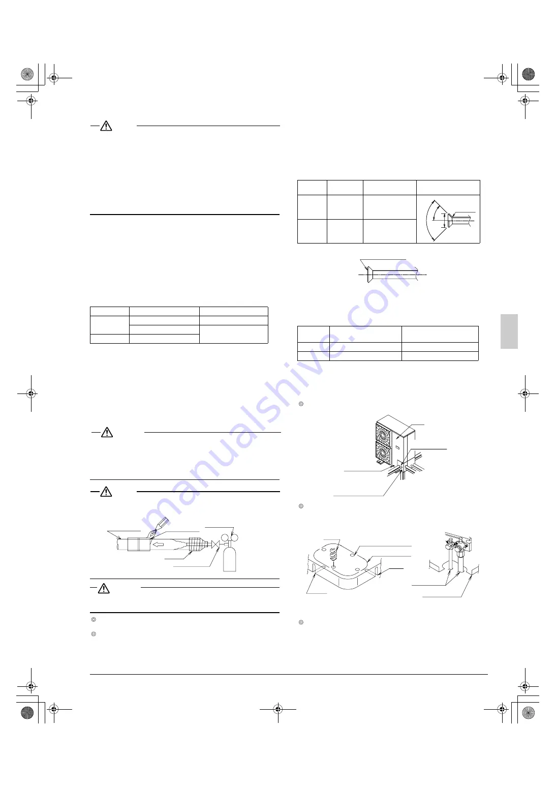
6-4 Refrigerant piping work procedure
The field piping can be connected in four directions.
When connecting the piping downward, remove the knockout hole by
making four holes in the middle on the each side of the knockout hole
with a drill.
Then cut out the corner of the bottom frame along the slits (in two
positions) by using a hacksaw.
After removing the parts, it is recommended to apply repair paint on
the edges, to prevent rusting.
Location
Working period
Protection method
Outdoor
1 month or more
Pinch pipes
Less than 1 month
Pinch or tape pipes
Indoor
Regardless of period
Location to
be brazed
Taping
Refrigerant
piping
Nitrogen
Regulator
Manual valve
Nitrogen
Pipe size
Tightening
torque (ft·lbf)
Flare dimension A (in.)
Flare shape (in.)
φ
3/8”
24.1 - 29.4
0.504 - 0.520
φ
5/8”
45.6-55.6
0.760 - 0.776
Pipe size
Tightening angle
(Guideline)
Recommended arm
length of tool (in.)
φ
3/8”
60°~90°
Approx. 7 7/8
φ
5/8”
30°~60°
Approx. 11 13/16
A
45˚± 2˚
90˚± 2˚
R0.016
~0.031
Ester or ether oil
Piping cover
Screw for
front panel
Screw for piping
cover (front)
Front
panel
Lateral
direction
Front direction
Rear
direction
Downward
direction
Field piping
Bottom frame
Knockout hole
Drill
Slit
Middle on the side
Slit
01_EN_3PN07193-7H.fm Page 8 Monday, December 27, 2010 4:30 PM


