


4 Installation
Installation manual
6
RZQG7 RZQG71~12 RZQG140L7Y1L
Split system air conditioners
4P473073-1A – 2019.04
5
If the outdoor unit is installed above the indoor unit, cover the
stop valves (f, see above) with sealing material to prevent
condensed water on the stop valves from moving to the indoor
unit.
NOTICE
Any exposed piping might cause condensation.
6
Reattach the service cover and the piping intake plate.
7
Seal all gaps (example: a) to prevent snow and small animals
from entering the system.
a
WARNING
Provide adequate measures to prevent that the unit can be
used as a shelter by small animals. Small animals that
make contact with electrical parts can cause malfunctions,
smoke or fire.
NOTICE
Make sure to open the stop valves after installing the
refrigerant piping and performing vacuum drying. Running
the system with the stop valves closed may break the
compressor.
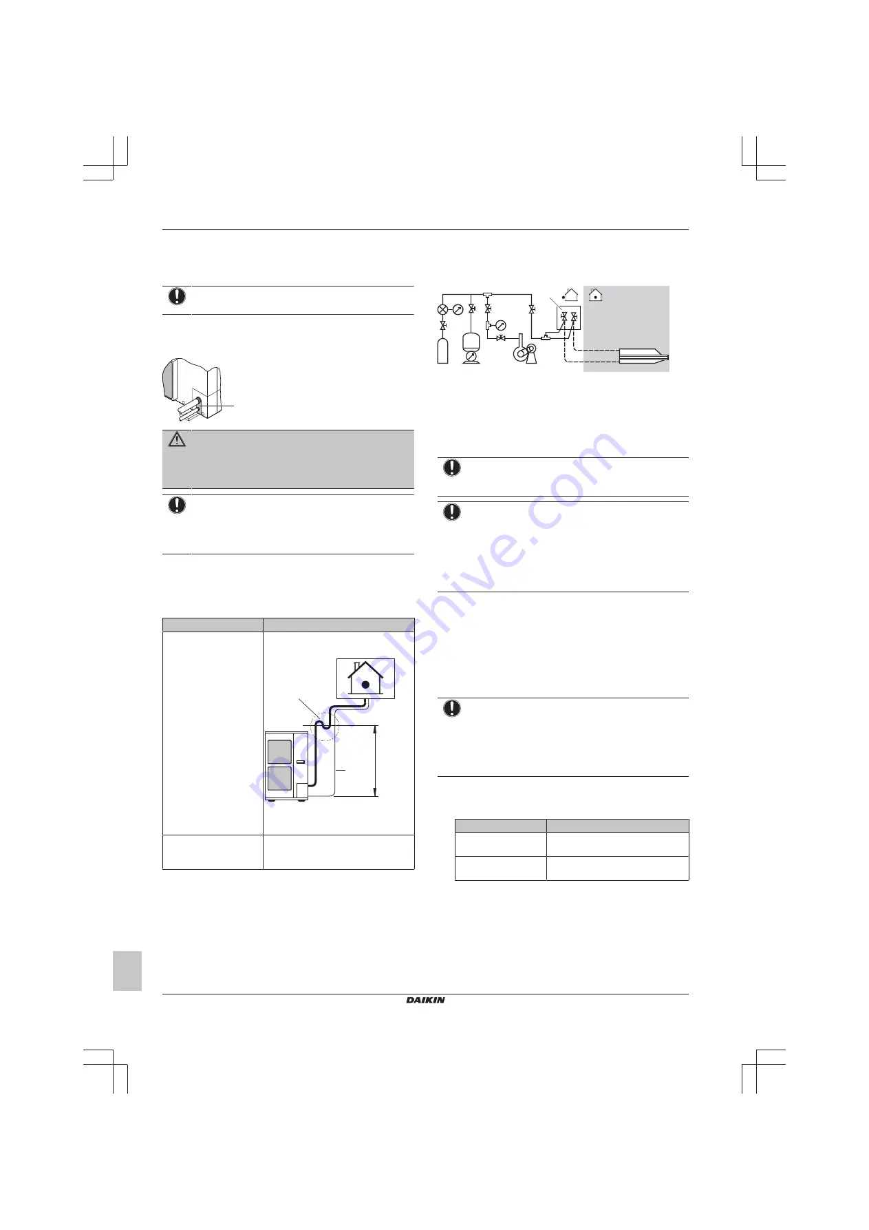
4.2.2
To determine if oil traps are required
If oil flows back into the outdoor unit's compressor, this might cause
liquid compression or deterioration of oil return. Oil traps in the rising
gas piping can prevent this.
If
Then
The indoor unit is installed
higher than the outdoor
unit
Install an oil trap every 10 m (height
difference).
a
b
10 m
a
Rising gas piping with oil trap
b
Liquid piping
The outdoor unit is
installed higher than the
indoor unit
Oil traps are NOT required.
4.3
Checking the refrigerant piping
4.3.1
Checking refrigerant piping: Setup
a
c
f
b
d
e
R410A
a
Pressure gauge
b
Nitrogen
c
Refrigerant
d
Weighing machine
e
Vacuum pump
f
Stop valve
4.3.2
To check for leaks
NOTICE
Do NOT exceed the unit's maximum working pressure (see
"PS High" on the unit name plate).
NOTICE
Make sure to use a recommended bubble test solution
from your wholesaler. Do not use soap water, which may
cause cracking of flare nuts (soap water may contain salt,
which absorbs moisture that will freeze when the piping
gets cold), and/or lead to corrosion of flared joints (soap
water may contain ammonia which causes a corrosive
effect between the brass flare nut and the copper flare).
1
Charge the system with nitrogen gas up to a gauge pressure of
at least 200 kPa (2 bar). It is recommended to pressurize to
3000 kPa (30 bar) in order to detect small leaks.
2
Check for leaks by applying the bubble test solution to all
connections.
3
Discharge all nitrogen gas.
4.3.3
To perform vacuum drying
NOTICE
▪ Connect the vacuum pump to
both
the service port of
the gas stop valve and the service port of the liquid
stop valve to increase efficiency.
▪ Make sure that the gas stop valve and liquid stop valve
are firmly closed before performing the leak test or
vacuum drying.
1
Vacuum the system until the pressure on the manifold indicates
−0.1 MPa (−1 bar).
2
Leave as is for 4-5 minutes and check the pressure:
If the pressure…
Then…
Does not change
There is no moisture in the system.
This procedure is finished.
Increases
There is moisture in the system. Go
to the next step.
3
Vacuum the system for at least 2 hours to a manifold pressure
of −0.1 MPa (−1 bar).
4
After turning the pump OFF, check the pressure for at least
1 hour.
5
If you do NOT reach the target vacuum or CANNOT maintain
the vacuum for 1 hour, do the following:
▪ Check for leaks again.
▪ Perform vacuum drying again.
Summary of Contents for RZQG71L9V1L
Page 14: ......
Page 15: ......
Page 16: ...4P473073 1A 2019 04 Copyright 2017 Daikin 4P473073 1 A 0000000...


