Installation manual
9
RZQG71~140L + RZQSG100~140L
Split system air conditioners
4P339538-1A – 2014.03
9.
Precautions on refrigerant piping
Do not allow anything other than the designated refrigerant to
get mixed into the freezing cycle, such as air, etc. If any
refrigerant gas leaks while working on the unit, ventilate the
room thoroughly right away.
Use R410A only when adding refrigerant
Installation tools:
Make sure to use installation tools (gauge manifold, charge
hose, etc.) that are exclusively used for R410A installations to
withstand the pressure and to prevent foreign materials (e.g.
mineral oils and moisture) from mixing into the system.
Vacuum pump:
Use a 2-stage vacuum pump with a non-return valve
Make sure the pump oil does not flow oppositely into the system
while the pump is not working.
Use a vacuum pump which can evacuate to –100.7 kPa (5 Torr,
–755 mm Hg).
During tests never pressurize the appliances with a pressure
higher than the maximum allowable pressure (see unit name
plate: PS).
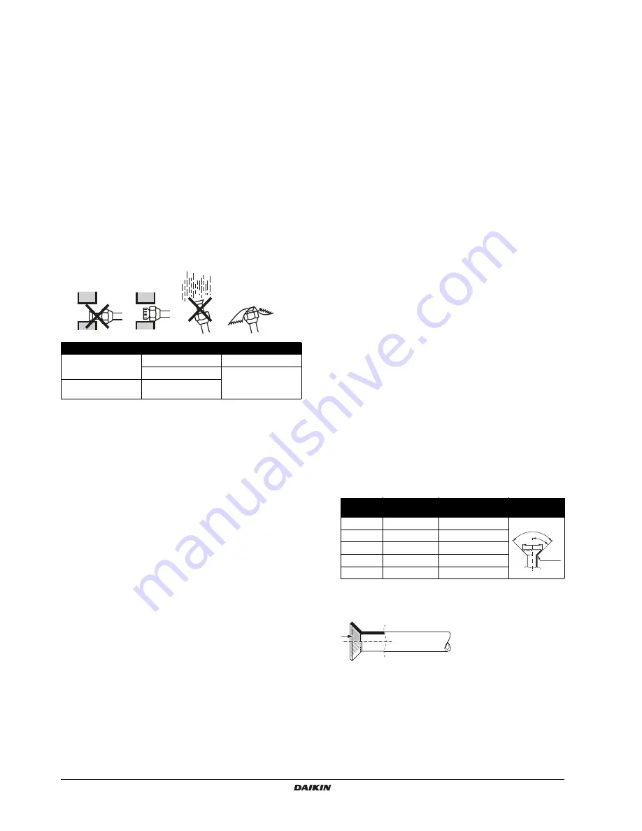
In order to prevent dirt, liquid or dust from entering the piping,
cure the piping with a pinch or taping.
Great caution is needed when passing copper tubes through
walls.
Piping should be mounted so that the flare is not subjected to
mechanical stress.
In case of simultaneous operating system
- Upward and downward piping should be performed at the
main piping line.
- Use branch piping kit (optional) for branching refrigerant
pipes.
Precautions to be taken. (For details, refer to the manual attached to
branch piping kit.)
- Install the branch pipes horizontally (with a maximum
inclination of 15°) or vertically.
- Length of branch pipe to the indoor unit should be as short as
possible.
- Try to keep lengths of both branch pipes to the indoor unit
equal.
When using existing refrigerant piping
Pay attention to the following points when using existing
refrigerant piping
Perform a visual check on quality of residual oil in existing
refrigerant piping.
This check is extremely important because using existing
piping with deteriorated oil will cause compressor
breakdown.
-
Put some residual oil of the pipes you want to reuse on a
piece of white paper or on the white surface of an oil
checking reference card and compare that oil colour with
the circled colour of the oil checking reference card.
-
If oil colour is identical to the circled colour or darker,
replace the piping, install new piping or clean the piping
thoroughly.
-
If oil colour is lighter, the pipes can be reused without
cleaning.
An oil checking reference card is indispensable for such
evaluation and can be obtained at your dealer.
In the following situations, the existing piping should not be
re-used and new piping should be installed.
-
If the previously used model had problems with its
compressor (this might cause oxidised coolant oil, scale
residue and other adverse effects).
-
If the indoor or outdoor units were disconnected from the
piping for a long period of time (water or dirt might have
gotten into the piping).
-
If copper piping is corroded.
Flares should not be re-used but rather new ones made in
order to prevent leaks.
Check welded connections for gas leaks, if the local piping
has welded connections.
Replace deteriorated insulation with new material.
9.1.
Flaring guidelines
Flares should not be re-used. New ones should be made in
order to prevent leaks.
Use a pipe cutter and flare tool suitable for the refrigerant used.
Only use the flare nuts included with the unit. Using different
flare nuts may cause the refrigerant to leak.
Please refer to the table for flaring dimensions and tightening
torques (too much tightening will result in splitting the flare).
When connecting the flare nut, coat the flare inner surface with
ether oil or with ester oil and initially tighten 3 or 4 turns by hand
before tightening firmly.
Place
Installation period
Protection method
Outdoor unit
More than a month
Pinch the pipe
Less than a month
Pinch or tape the pipe
Indoor unit
Regardless of the
period
Piping size
(mm)
Tightening
torque (N•m)
Flare dimensions A
(mm)
Flare shape
(mm)
Ø6.4
15~17
8.7~9.1
Ø9.5
33~39
12.8~13.2
Ø12.7
50~60
16.2~16.6
Ø15.9
63~75
19.3~19.7
Ø19.1
90~110
23.6~24.0
A
90
2
45
2
R=0.4~0.8


