background image

6 Installation

Installer and user reference guide

20

RXYSQ4~6TAY1B

VRV IV-S system air conditioner

4P482257-1 – 2017.03

6

Seal  all  gaps  (example:  a)  to  prevent  snow  and  small  animals
from entering the system.

a

WARNING

Provide adequate measures to prevent that the unit can be
used  as  a  shelter  by  small  animals.  Small  animals  that
make contact with electrical parts can cause malfunctions,
smoke or fire.

NOTICE

Make  sure  to  open  the  stop  valves  after  installing  the
refrigerant  piping  and  performing  vacuum  drying.  Running
the  system  with  the  stop  valves  closed  may  break  the
compressor.

6.4.8

To connect the refrigerant branching kit

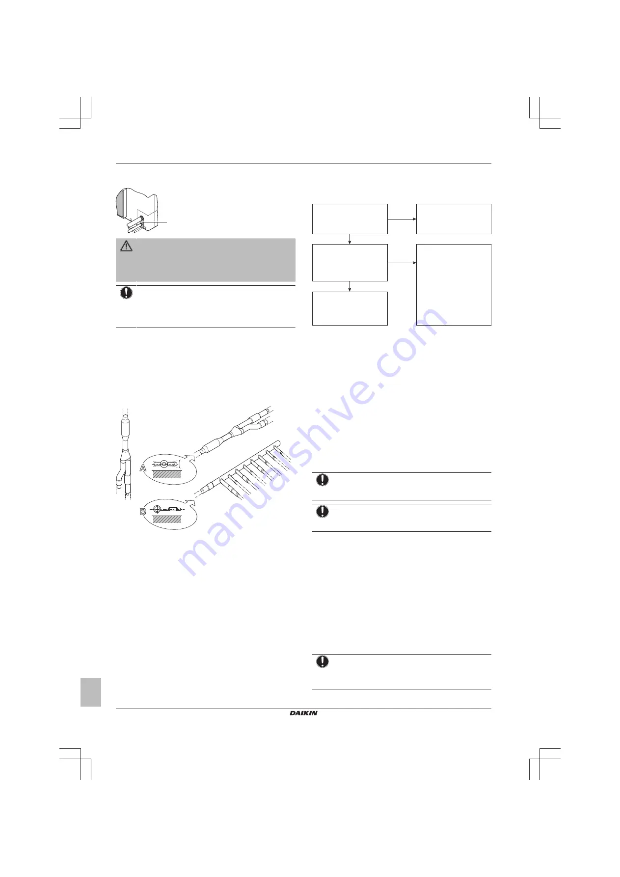
For installation of the refrigerant branching kit, refer to the installation
manual delivered with the kit.

▪ Mount  the  refnet  joint  so  that  it  branches  either  horizontally  or

vertically.

▪ Mount the refnet header so that it branches horizontally.

A

B

±3

0

°

a

b

c

a

a

Horizontal surface

b

Refnet joint mounted vertically

c

Refnet joint mounted horizontally

6.5

Checking the refrigerant piping

6.5.1

About checking the refrigerant piping

Refrigerant piping works are 

finished?

The indoor units and/or 

outdoor unit were already 

powered ON?

Use procedure:
"Method 2: After power ON".

Finish piping work.

Use procedure:
"Method 1: Before power ON 

(regular method)".

Yes

No

No

Yes

It is very important that all refrigerant piping work is done before the
units (outdoor or indoor) are powered on.

When the units are powered on, the expansion valves will initialise.
This means that they will close. Leak test and vacuum drying of field
piping and indoor units is impossible when this happens.

Therefore,  there  will  be  explained  2  methods  for  initial  installation,
leak test and vacuum drying.

Method 1: Before power ON

If  the  system  has  not  yet  been  powered  on,  no  special  action  is
required to perform the leak test and the vacuum drying.

Method 2: After power ON

If  the  system  has  already  been  powered  on,  activate  setting  [2‑21]
(refer  to 

"7.2.4  To  access  mode  1  or  2"  on  page  28

).  This  setting

will  open  field  expansion  valves  to  guarantee  a  R410A  piping
pathway  and  make  it  possible  to  perform  the  leak  test  and  the
vacuum drying.

NOTICE

Make  sure  that  all  indoor  units  connected  to  the  outdoor
unit are powered on.

NOTICE

Wait  until  the  outdoor  unit  has  finished  the  initialisation  to
apply setting [2‑21].

Leak test and vacuum drying

Checking the refrigerant piping involves:

▪ Checking for any leakages in the refrigerant piping.

▪ Performing  vacuum  drying  to  remove  all  moisture,  air  or  nitrogen

in the refrigerant piping.

If  there  is  a  possibility  of  moisture  being  present  in  the  refrigerant
piping  (for  example,  water  may  have  entered  the  piping),  first  carry
out  the  vacuum  drying  procedure  below  until  all  moisture  has  been
removed.

All piping inside the unit has been factory tested for leaks.

Only  field  installed  refrigerant  piping  needs  to  be  checked.
Therefore, make sure that all the outdoor unit stop valves are firmly
closed before performing leak test or vacuum drying.

NOTICE

Make  sure  that  all  (field  supplied)  field  piping  valves  are
OPEN (not outdoor unit stop valves!) before you start leak
test and vacuuming.

Summary of Contents for RXYSQ5TAY1B

Page 1: ...Installer and user reference guide VRV IV S system air conditioner English Installer and user reference guide VRV IV S system air conditioner RXYSQ4TAY1B RXYSQ5TAY1B RXYSQ6TAY1B...

Page 2: ...6 4 5 Using the stop valve and service port 17 6 4 6 To remove the pinched pipes 18 6 4 7 To connect the refrigerant piping to the outdoor unit 19 6 4 8 To connect the refrigerant branching kit 20 6 5...

Page 3: ...not work 53 20 2 3 Symptom The fan strength does not correspond to the setting 54 20 2 4 Symptom The fan direction does not correspond to the setting 54 20 2 5 Symptom White mist comes out of a unit...

Page 4: ...ste batteries are disposed of correctly you will help to prevent potential negative consequences for the environment and human health 1 3 For the installer 1 3 1 General If you are not sure how to ins...

Page 5: ...ave to operate WARNING Always recover the refrigerant Do NOT release them directly into the environment Use a vacuum pump to evacuate the installation NOTICE After all the piping has been connected ma...

Page 6: ...tor Failure to do so may cause electric shock or fire When installing the earth leakage protector make sure it is compatible with the inverter resistant to high frequency electric noise to avoid unnec...

Page 7: ...hat you have to do after the box with the outdoor unit is delivered on site It contains information about Unpacking and handling the units Removing the accessories from the units Keep the following in...

Page 8: ...utdoor installation and aimed for air to air heat pump applications Specification RXYSQ4 6 Capacity Heating 14 2 18 0 kW Cooling 12 1 15 5 kW Ambient design temperature Heating 20 15 5 C WB Cooling 5...

Page 9: ...g works where a lot of dust is created the unit must be covered Choose the installation location with sufficient place for carrying the unit in and out of the site 5 2 1 Installation site requirements...

Page 10: ...the outdoor unit is exposed to direct sea winds install a windbreaker Height of windbreaker 1 5 height of outdoor unit Mind the service space requirements when installing the windbreaker a b c d c d...

Page 11: ...d leak The unit of measurement of the concentration is kg m3 the weight in kg of the refrigerant gas in 1 m3 volume of the occupied space Compliance to the local applicable regulations and standards f...

Page 12: ...6 4 mm 1 4 9 5 mm 3 8 12 7 mm 1 2 Annealed O 0 80 mm t 15 9 mm 5 8 Annealed O 0 99 mm 19 1 mm 3 4 22 2 mm 7 8 Half hard 1 2H 0 80 mm a Depending on the applicable legislation and the unit s maximum w...

Page 13: ...ge 12 Refnet joint at first branch counting from outdoor unit When using refnet joints at the first branch counted from the outdoor unit side choose from the following table in accordance with the cap...

Page 14: ...imum height difference indoor indoor Examples H2 Limit 15 m 15 m Maximum height difference outdoor BP Example 2 H3 Limit N A 30 m Maximum height difference BP BP Example 2 H4 Limit N A 15 m Maximum he...

Page 15: ...r and all indoors 600 m If the total transmission wiring exceeds these limits it may result in communication error 6 Installation 6 1 Overview Installation This chapter describes what you have to do a...

Page 16: ...in order to avoid ice accumulation Prepare a water drainage channel around the foundation to drain waste water surrounding the unit Avoid drain water flowing over the footpath so that it does not beco...

Page 17: ...egardless of the period INFORMATION Do NOT open the refrigerant stop valve before checking the refrigerant piping When you need to charge additional refrigerant it is recommended to open the refrigera...

Page 18: ...ing the service port make sure to tighten the service port cover securely For the tightening torque refer to the table below Check for refrigerant leaks after tightening the service port cover Tighten...

Page 19: ...a with screw b a b 2 Choose a piping route a b c or d a b c d 3 If you have chosen the downwards piping route Drill a 4 and remove the knockout hole b Cut out the slits c with a metal saw c c b a 4 6...

Page 20: ...ll initialise This means that they will close Leak test and vacuum drying of field piping and indoor units is impossible when this happens Therefore there will be explained 2 methods for initial insta...

Page 21: ...est for leaks by applying a bubble test solution to all piping connections 3 Discharge all nitrogen gas NOTICE Make sure to use a recommended bubble test solution from your wholesaler Do not use soap...

Page 22: ...perly NOTICE Be sure to turn on the power 6 hours before operation in order to have power running to the crankcase heater and to protect the compressor NOTICE If operation is performed within 12 minut...

Page 23: ...refrigerant in manual additional refrigerant charge mode instructions Charging refrigerant in manual additional refrigerant charge mode The remaining additional refrigerant charge can be charged by op...

Page 24: ...onsists of the following stages 1 Making sure the power supply system complies with the electrical specifications of the units 2 Connecting the electrical wiring to the outdoor unit 3 Connecting the e...

Page 25: ...tor Install power cables at least 1 metre away from televisions or radios to prevent interference Depending on the radio waves a distance of 1 metre may not be sufficient WARNING After finishing the e...

Page 26: ...ical wiring on the outdoor unit NOTICE Follow the wiring diagram delivered with the unit located at the inside of the service cover Make sure the electrical wiring does NOT obstruct proper reattachmen...

Page 27: ...e as shown in figure below a b c d e a Liquid pipe b Gas pipe c Insulator d Transmission wiring F1 F2 e Finishing tape 6 9 2 To close the outdoor unit NOTICE When closing the outdoor unit cover make s...

Page 28: ...SET For field setting BS3 RETURN For field setting BS4 TEST For test operation BS5 RESET For resetting the address when the wiring is changed or when an additional indoor unit is installed Display Th...

Page 29: ...lay Mode 2 You can change the value of setting 2 8 Te target temperature during cooling operation to 4 8 C as follows Action Button display 1 Start from the default situation 2 Select mode 2 BS1 5 s 3...

Page 30: ...ecked again through this monitoring settings For the content or reason behind the malfunction code see 11 3 Solving problems based on error codes on page 38 where most relevant malfunction codes are e...

Page 31: ...ow noise setting and level during night time By changing this setting you activate the automatic low noise operation function of the unit and define the level of operation Depending on the chosen leve...

Page 32: ...y consumption and comfort No matter which control is selected variations on the behaviour of the system are still possible due to protection controls to keep the unit operating under reliable conditio...

Page 33: ...se of cooling operation the evaporating temperature is allowed to go down to 6 C on temporary base depending on the situation In case of heating operation the condense temperature is allowed to go up...

Page 34: ...orating temperature Quick Powerful Mild Room temperature evolution A B C D E F A Indoor unit set temperature B Operation start C Operating time D Mild E Quick F Powerful 7 3 4 Example Automatic mode d...

Page 35: ...ting up the unit Field wiring Be sure that the field wiring has been carried out according to the instructions described in the chapter 6 8 Connecting the electrical wiring on page 24 according to the...

Page 36: ...essure equalisation Cooling start up control Cooling stable condition Communication check Stop valve check Pipe length check Pump down operation Unit stop INFORMATION During the test operation it is n...

Page 37: ...al operation will not be performed For details refer to the wiring diagram labelled on the back of the service cover Pay attention to the fan It is dangerous to inspect the unit while the fan is runni...

Page 38: ...vercharge Open the stop valve on both the gas and liquid side Recalculate the required amount of refrigerant from the piping length and correct the refrigerant charge level by recovering any excessive...

Page 39: ...or unit is connected correctly Faulty wiring to Q1 Q2 Check Q1 Q2 wiring System mismatch Wrong type of indoor units combined R410A R407C RA etc Indoor unit malfunction Check if other indoor units have...

Page 40: ...diagram Wiring diagram 13 2 Dimensions Outdoor unit dimensions in mm 191 142 67 95 940 223 30 16 55 350 160 95 61 55 145 160 30 68 89 84 68 19 48 44 53 90 13 67 80 54 395 47 52 1430 54 95 60 320 89 6...

Page 41: ...B HU HB HD HD HU 100 1000 1000 500 HU HD HU 200 1000 1000 500 HD HU 200 1700 1000 500 HU a b 100 100 c d e eB eD A B C D E HB HD A B C 200 300 1000 A B C E 200 300 1000 1000 500 D 1000 D E 1000 1000 5...

Page 42: ...A1 If there is danger of drainage dripping and freezing between the upper and lower units A2 Then install a roof between the upper and lower units Install the upper unit high enough above the lower u...

Page 43: ...erant charge f Stop valve gas g Stop valve liquid h Cable tie mountings to fix the field wiring with cable ties to ensure stress relief i Subcool heat exchanger j Accumulator k Fan A1P Printed circuit...

Page 44: ...g Heat exchanger h Service port high pressure i Oil separator j Capillary tube 2 k Service port refrigerant charge M1C Compressor M1F M2F Fan motor R1T Thermistor air R2T Thermistor suction 1 R3T The...

Page 45: ...HT RED TO MULTI UNIT TO OUT D TO IN D INDOOR OUTDOOR Note 5 TERMINAL OF M1C LAYOUTOF M1F M2F M1C L1R EL COMPO BOX DETAILOF EL COMPO BOX ARROW VIEW OUTER SHELL FRONT MARK BLU MARK RED MARK RED EL COMPO...

Page 46: ...stor air R2T Thermistor suction 1 R3T Thermistor discharge R4T Thermistor heat exchanger de icer R5T Thermistor subcool heat exchanger R6T Thermistor liquid pipe R7T Thermistor suction 2 S1NPH High pr...

Page 47: ...ired to connect Residential Air RA or Sky Air SA direct expansion DX indoor units f Residential Air RA direct expansion DX indoor units g User interface wireless dedicated depending on indoor unit typ...

Page 48: ...ation the refrigerant cycle will reverse and energy from inside the building will be used to defrost the outdoor unit coil The indoor unit will indicate defrost operation on the displays Hot start In...

Page 49: ...user interfaces as the master user interface The displays of slave user interfaces show change over under centralised control and slave user interfaces automatically follow the operation mode directed...

Page 50: ...ation methods Basic The refrigerant temperature is fixed independent from the situation It corresponds to the standard operation which is known and can be expected from under previous VRV systems Auto...

Page 51: ...unit Do not use the system until a service person confirms that the portion where the refrigerant leaks is repaired 19 4 After sales service and warranty 19 4 1 Warranty period This product includes...

Page 52: ...oting If one of the following malfunctions occur take the measures shown below and contact your dealer WARNING Stop operation and shut off the power if anything unusual occurs burning smells etc Leavi...

Page 53: ...on outdoor De icing temperature sensor malfunction outdoor Liquid temperature sensor after subcool HE malfunction outdoor Liquid temperature sensor coil malfunction outdoor Gas temperature sensor afte...

Page 54: ...stop When the drain pump optional accessories is in operation this noise is heard A pishi pishi squeaking sound is heard when the system stops after heating operation Expansion and contraction of pla...

Page 55: ...relevant and applicable for a certain product or domain Service company Qualified company which can perform or coordinate the required service to the product Installation manual Instruction manual sp...

Page 56: ...4P482257 1 2017 03 Copyright 2017 Daikin...

Reviews: