background image

6 Installation

Installer and user reference guide

22

RXYSQ4~Y1B

VRV IV-S system air conditioner

4P404676-1A – 2016.03

6.5.5

To perform vacuum drying

NOTICE

The  connections  to  the  indoor  units  and  all  indoor  units
should  also  be  leak  and  vacuum  tested.  Keep,  if  existing,
all  (field  supplied)  field  valves  to  the  indoor  units  open  as
well.

Leak  test  and  vacuum  drying  should  be  done  before  the
power  supply  is  set  to  the  unit.  If  not,  see 

"6.5.1  About

checking  the  refrigerant  piping"  on  page  20

  for  more

information.

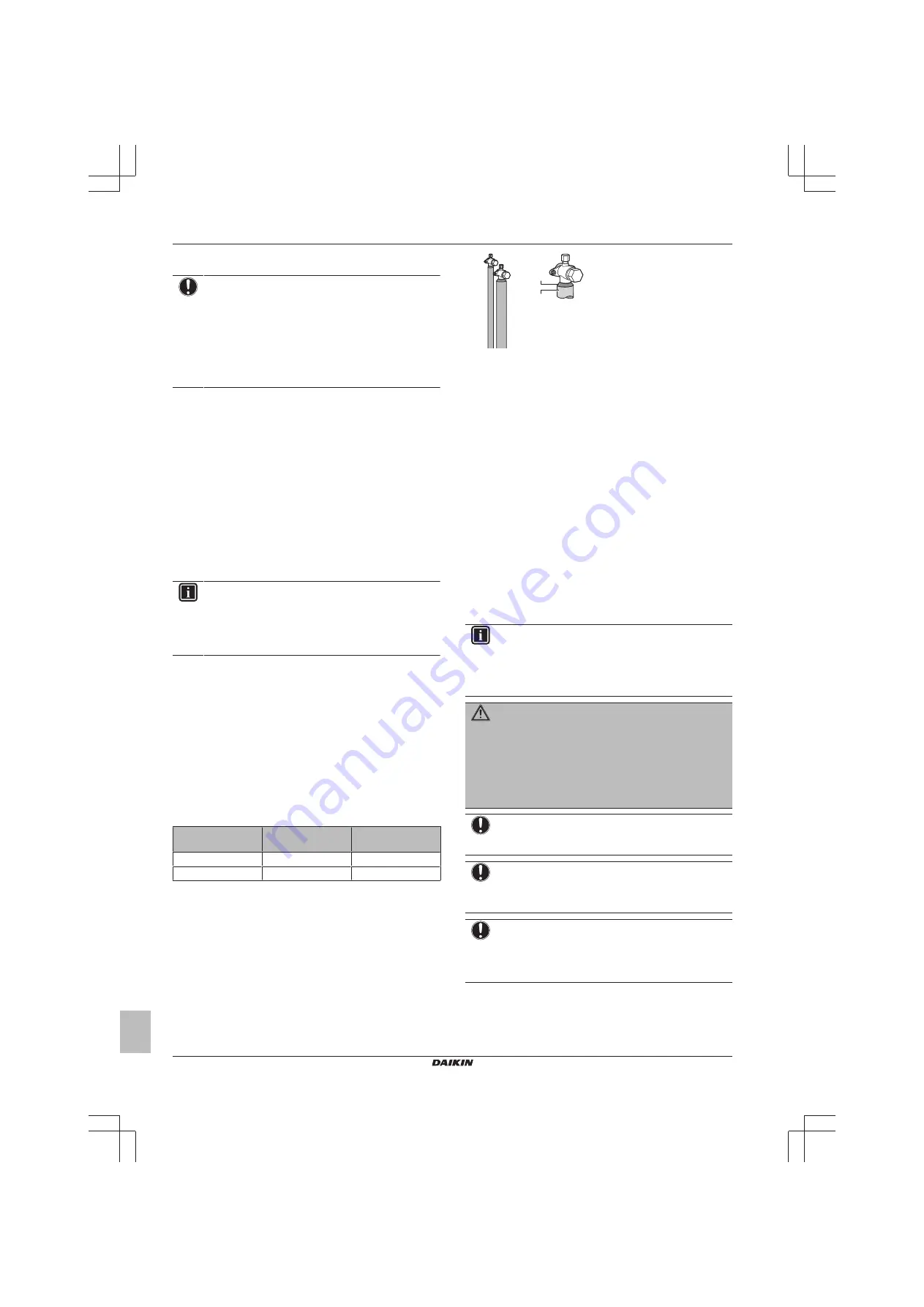
To remove all moisture from the system, proceed as follows:

1

Evacuate the system for at least 2 hours to a target vacuum of
–⁠100.7 kPa (–⁠1.007 bar/5 Torr).

2

Check  that,  with  the  vacuum  pump  turned  off,  the  target
vacuum is maintained for at least 1 hour.

3

Should  you  fail  to  reach  the  target  vacuum  within  2  hours  or
maintain  the  vacuum  for  1  hour,  the  system  may  contain  too
much moisture. In that case, break the vacuum by pressurising
with  nitrogen  gas  to  a  gauge  pressure  of  0.05  MPa  (0.5  bar)
and repeat steps 1 to 3 until all moisture has been removed.

4

Depending  on  whether  you  want  to  immediately  charge
refrigerant through the refrigerant charge port or first pre-charge
a  portion  of  refrigerant  through  the  liquid  line,  either  open  the
outdoor  unit  stop  valves,  or  keep  them  closed.  See 

"6.7.4  To

charge refrigerant" on page 23

 for more information.

INFORMATION

After opening the stop valve, it is possible that the pressure
in the refrigerant piping does NOT increase. This might be
caused  by  e.g.  the  closed  state  of  the  expansion  valve  in
the outdoor unit circuit, but does NOT present any problem
for correct operation of the unit.

6.6

To insulate the refrigerant piping

After  finishing  the  leak  test  and  vacuum  drying,  the  piping  must  be
insulated. Take into account the following points:

▪ Make sure to insulate the connection piping and refrigerant branch

kits entirely.

▪ Be sure to insulate the liquid and gas piping (for all units).

▪ Use  heat  resistant  polyethylene  foam  which  can  withstand  a

temperature of 70°C for liquid piping and polyethylene foam which
can withstand a temperature of 120°C for gas piping.

▪ Reinforce the insulation on the refrigerant piping according to the

installation environment.

Ambient

temperature

Humidity

Minimum thickness

≤30°C

75% to 80% RH

15 mm

>30°C

≥80% RH

20 mm

Condensation might form on the surface of the insulation.

▪ If  there  is  a  possibility  that  condensation  on  the  stop  valve  might

drip  down  into  the  indoor  unit  through  gaps  in  the  insulation  and
piping  because  the  outdoor  unit  is  located  higher  than  the  indoor
unit,  this  must  be  prevented  by  sealing  up  the  connections.  See
below figure.

b

a

a

Insulation material

b

Caulking etc.

6.7

Charging refrigerant

6.7.1

About charging refrigerant

The  outdoor  unit  is  factory  charged  with  refrigerant,  but  depending
on the field piping you have to charge additional refrigerant.

Before charging refrigerant

Make  sure  the  outdoor  unit's 

external

  refrigerant  piping  is  checked

(leak test, vacuum drying).

Typical workflow

Charging  additional  refrigerant  typically  consists  of  the  following
stages:

1

Determining how much you have to charge additionally.

2

Charging additional refrigerant (pre-charging and/or charging).

3

Filling in the fluorinated greenhouse gases label, and fixing it to
the inside of the outdoor unit.

6.7.2

Precautions when charging refrigerant

INFORMATION

Also  read  the  precautions  and  requirements  in  the
following chapters:

▪ General safety precautions

▪ Preparation

WARNING

▪ Only use R410A as refrigerant. Other substances may

cause explosions and accidents.

▪ R410A  contains  fluorinated  greenhouse  gases.  Its

global  warming  potential  (GWP)  value  is  2087.5.  Do
NOT vent these gases into the atmosphere.

▪ When  charging  refrigerant,  always  use  protective

gloves and safety glasses.

NOTICE

If  the  power  of  some  units  is  turned  off,  the  charging
procedure cannot be finished properly.

NOTICE

Be  sure  to  turn  on  the  power  6  hours  before  operation  in
order  to  have  power  running  to  the  crankcase  heater  and
to protect the compressor.

NOTICE

If operation is performed within 12 minutes after the indoor
and  outdoor  units  are  turned  on,  the  compressor  will  not
operate  before  the  communication  is  established  in  a
correct way between outdoor unit(s) and indoor units.

Summary of Contents for RXYSQ4T7V1B

Page 1: ...er and user reference guide VRV IV S system air conditioner English Installer and user reference guide VRV IV S system air conditioner RXYSQ4T7V1B RXYSQ5T7V1B RXYSQ6T7V1B RXYSQ4T7Y1B RXYSQ5T7Y1B RXYSQ...

Page 2: ...the pipe end 18 6 4 6 To braze the pipe end 18 6 4 7 Using the stop valve and service port 18 6 4 8 To connect the refrigerant piping to the outdoor unit 19 6 4 9 To connect the refrigerant branching...

Page 3: ...4 Shortened maintenance and replacement cycles 59 20 Troubleshooting 60 20 1 Error codes Overview 60 20 2 Symptoms that are not air conditioner troubles 61 20 2 1 Symptom The system does not operate...

Page 4: ...to prevent potential negative consequences for the environment and human health 1 3 For the installer 1 3 1 General If you are not sure how to install or operate the unit contact your dealer NOTICE I...

Page 5: ...n the refrigerant system is to be opened refrigerant must be treated according to the applicable legislation WARNING Make sure there is no oxygen in the system Refrigerant may only be charged after pe...

Page 6: ...inverter resistant to high frequency electric noise to avoid unnecessary opening of the earth leakage protector NOTICE Precautions when laying power wiring Do not connect wiring of different thickness...

Page 7: ...after the box with the outdoor unit is delivered on site It contains information about Unpacking and handling the units Removing the accessories from the units Keep the following in mind At delivery...

Page 8: ...OTICE When installing or servicing several units at the same time make sure NOT to switch the service panels between different models 4 2 1 Identification label Outdoor unit Location Model identificat...

Page 9: ...g kit Description Model name Refnet header KHRQ22M29H Refnet joint KHRQ22M20T For the selection of the optimal branching kit please refer to 5 3 4 To select refrigerant branch kits on page 13 Cool hea...

Page 10: ...nditions the measured value might be higher than the sound pressure level mentioned in Sound spectrum in the data book due to environmental noise and sound reflections In places where a mineral oil mi...

Page 11: ...ring safety against refrigerant leaks About safety against refrigerant leaks The installer and system specialist shall secure safety against leakage according to local regulations or standards The fol...

Page 12: ...of the above calculation exceeds the maximum concentration level a ventilation opening to the adjacent room shall be made Formula F G H F Total volume of refrigerant in the refrigerant system G Size...

Page 13: ...up If the recommended gas pipe size up is not available you must use the standard size which might result in a small capacity decrease a e b c d a Outdoor unit b Main gas pipe c Increase d First refri...

Page 14: ...mple 1 3 unit 8 a i Limit Example 2 unit 18 a b m Limit 120 m 65 m Maximum equivalent piping length a 150 m 85 m Maximum total piping length Example 1 1 a b c d e f g h i j k l m n p Limit Example 2 a...

Page 15: ...table below Model Minimum circuit ampacity Recommended fuses Power supply RXYSQ4_V1 29 1 A 32 A 1 50 Hz 220 240 V RXYSQ5_V1 RXYSQ6_V1 RXYSQ4_Y1 14 1 A 16 A 3N 50 Hz 380 415 V RXYSQ5_Y1 RXYSQ6_Y1 Tran...

Page 16: ...tion 6 3 3 To provide the installation structure Check the strength and level of the installation ground so that the unit will not cause any operating vibration or noise Fix the unit securely by means...

Page 17: ...the outdoor unit Connecting refrigerant branch kits Connecting the refrigerant piping to the indoor units see the installation manual of the indoor units Insulating the refrigerant piping Keeping in...

Page 18: ...the pipe 4 Flare the pipe Set exactly at the position as shown in the following illustration A Conventional flare tool Flare tool for R410A clutch type Clutch type Ridgid type Wing nut type Imperial t...

Page 19: ...w Check for refrigerant leaks after tightening the stop valve cover To handle the service port Always use a charge hose equipped with a valve depressor pin since the service port is a Schrader type va...

Page 20: ...at make contact with electrical parts can cause malfunctions smoke or fire NOTICE Make sure to open the stop valves after installing the refrigerant piping and performing vacuum drying Running the sys...

Page 21: ...can evacuate to a gauge pressure of 100 7 kPa 5 Torr absolute NOTICE Make sure the pump oil does not flow oppositely into the system while the pump is not working NOTICE Do not purge the air with ref...

Page 22: ...for liquid piping and polyethylene foam which can withstand a temperature of 120 C for gas piping Reinforce the insulation on the refrigerant piping according to the installation environment Ambient...

Page 23: ...ring data Used indoor units Total capacity CR a Allowable capacity connection ratio VRV DX RA DX VRV DX 50 130 50 130 RA DX 80 130 80 130 a CR Connection ratio 6 7 4 To charge refrigerant To speed up...

Page 24: ...damage the compressor NOTICE After adding the refrigerant do not forget to close the lid of the refrigerant charging port The tightening torque for the lid is 11 5 to 13 9 N m 6 7 5 Error codes when c...

Page 25: ...mmunication error No branching is allowed after branching A B C b2 b3 c1 c2 b1 a A Outdoor unit B Indoor unit C Central user interface etc a Main line b1 b2 b3 Branch lines c1 c2 No branch is allowed...

Page 26: ...holes Avoid damaging the casing After making the knockout holes we recommend you remove the burrs and paint the edges and areas around the edges using repair paint to prevent rusting When passing elec...

Page 27: ...2 TO IN D UNIT V1 Y1 F1 F2 F1 F2 TO IND TO OUTD TO OUT D UNIT a a a Earth 4 Connect the power supply as follows 1 50 Hz 220 240 V L L N V1 Y1 X1M 3N 50 Hz 380 415 V L1 L2 L3 L1 L2 L3 N X1M a b c a Ear...

Page 28: ...ion This chapter describes what you have to do and know to configure the system after it is installed It contains information about Making field settings Energy saving and optimum operation INFORMATIO...

Page 29: ...TORY SETTING Push buttons Use the push buttons to make the field settings Operate the push buttons with an insulated stick such as a closed ball point pen to avoid touching of live parts BS1 MODE For...

Page 30: ...splay Mode 2 You can change the value of setting 2 8 Te target temperature during cooling operation to 4 8 C as follows Action Button display 1 Start from the default situation 2 Select mode 2 BS1 5 s...

Page 31: ...terface they can be checked again through this monitoring settings For the content or reason behind the malfunction code see 11 3 Solving problems based on error codes on page 39 where most relevant m...

Page 32: ...the level of operation Depending on the chosen level the noise level will be lowered The start and stop moments for this function are defined under setting 2 26 and 2 27 default Deactivated Level 1 Le...

Page 33: ...ergy consumption and comfort for the particular application Several patterns are available and explained below Modify the parameters to the needs of your building and to realize the best balance betwe...

Page 34: ...2 8 Heating operation 2 42 3 This setting is used in conjunction with setting 2 9 Quick Overshoot during heating operation or undershoot during cooling operation is allowed compared to the requested...

Page 35: ...vaporating temperature Quick Powerful Mild Room temperature evolution A B C D E F A Indoor unit set temperature B Operation start C Operating time D Mild E Quick F Powerful 7 3 4 Example Automatic mod...

Page 36: ...d abnormal noises and vibrations when starting up the unit Field wiring Be sure that the field wiring has been carried out according to the instructions described in the chapter 6 8 Connecting the ele...

Page 37: ...ssure equalisation Cooling start up control Cooling stable condition Communication check Stop valve check Pipe length check Pump down operation Unit stop INFORMATION During the test operation it is no...

Page 38: ...1F X107A for M2F 5 After the service is finished plug the junction connector back in Otherwise the malfunction code will be displayed and normal operation will not be performed For details refer to th...

Page 39: ...igerant charge level by recovering any excessive refrigerant with a refrigerant recovery machine The stop valve of an outdoor unit is left closed Insufficient refrigerant Open the stop valve on both t...

Page 40: ...Q2 wiring System mismatch Wrong type of indoor units combined R410A R407C RA etc Indoor unit malfunction Check if other indoor units have malfunction and confirm indoor unit mix is allowed Improper t...

Page 41: ...nsions in mm 140 620 140 350 345 355 40 94 43 59 30 320 30 900 1345 24 30 19 89 142 89 60 54 95 423 430 19 80 145 54 95 84 55 148 223 55 13 67 52 71 16 16 58 117 102 70 45 376 191 3TW30374 1D f a b c...

Page 42: ...HB HD HD HU 100 1000 1000 500 HU HD HU 200 1000 1000 500 HD HU 200 1700 1000 500 HU a b 100 100 c d e eB eD A B C D E HB HD A B C 200 300 1000 A B C E 200 300 1000 1000 500 D 1000 D E 1000 1000 500 B...

Page 43: ...A2 A1 If there is danger of drainage dripping and freezing between the upper and lower units A2 Then install a roof between the upper and lower units Install the upper unit high enough above the lowe...

Page 44: ...rvice port high pressure f Service port refrigerant charge g Cable tie mountings to fix the field wiring with cable ties to ensure stress relief h Stop valve gas i Stop valve liquid j Accumulator k Fa...

Page 45: ...Service port refrigerant charge f Cable tie mountings to fix the field wiring with cable ties to ensure stress relief g Stop valve gas h Stop valve liquid i Accumulator j Fan A1P Printed circuit boar...

Page 46: ...high pressure h Check valve i Compressor accumulator j Capillary tube k Service port refrigerant charge l Accumulator m Heat sink PCB only for RXYSQ4 6_V1 M1C Compressor M1F M2F Fan motor R1T Thermis...

Page 47: ...Heat Position in switchbox Upper side Front side Switch box Notes for RXYSQ4 6_V1 1 Symbols see below 2 For X37A refer to the installation manual of the option 3 Refer to the installation or service...

Page 48: ...r liquid pipe FINTH Thermistor fin S1NPH High pressure sensor S1NPL Low pressure sensor S1PH High pressure switch S1S Air control switch option S2S Cool heat selector switch option V1R IGBT power modu...

Page 49: ...n in switchbox Notes for RXYSQ4 6_Y1 1 Symbols see below 2 For X37A refer to the installation manual of the option 3 Refer to the installation or service manual on how to use BS1 BS4 push buttons and...

Page 50: ...pressure sensor S1NPL Low pressure sensor S1PH High pressure switch S1S Air control switch option S2S Cool heat selector switch option V1R IGBT power module A2P V2R V3R Diode module A2P X A PCB connec...

Page 51: ...0 kW COP 4 14 3 91 3 43 Heating nominal b Capacity 12 1 kW 14 0 kW 15 5 kW COP 4 52 4 28 3 90 PED Category 1 Most critical part Compressor PS V 167 bar l Maximum number of indoor units connected c 64...

Page 52: ...Nominal running current RLA a 14 0 A 17 3 A 21 2 A 4 44 A 5 55 A 6 84 A Starting current MSC b MCA MCA MCA MCA MCA MCA Minimum circuit amps MCA c 29 1 A 14 1 A Maximum fuse amps MFA d 32 A 16 A Total...

Page 53: ...s to be within the specified range The connection ratio CR 50 CR 130 HP class of outdoor unit 50 minimum CR VRV DX 80 minimum CR RA DX 100 nominal CR 130 maximum CR 4 50 80 100 130 5 62 5 100 125 162...

Page 54: ...ed to connect Residential Air RA or Sky Air SA direct expansion DX indoor units f Residential Air RA direct expansion DX indoor units g User interface wireless dedicated depending on indoor unit type...

Page 55: ...s air cooled coil increases over time restricting the energy transfer to the outdoor unit s coil Heating capability decreases and the system needs to go into defrost operation to be able to deliver e...

Page 56: ...n off power immediately after the unit stops but wait for at least 5 minutes 17 3 3 To use the dry program WITH cool heat changeover remote control switch To start 1 Select cooling operation mode with...

Page 57: ...er centralised control 17 5 3 To designate the master user interface RA DX In case only RA DX indoor units are connected to the VRV IV S system 1 Stop all indoor units 2 When the system is not operati...

Page 58: ...d The comfort level is related to the timing and the effort energy consumption which is put in achieving a certain room temperature by temporarily changing the refrigerant temperature to different val...

Page 59: ...he manufacturing number stated on the nameplate of the unit The installation date The symptoms or malfunction and details of the defect WARNING Do not modify disassemble remove reinstall or repair the...

Page 60: ...t operate at all Check if there is no power failure Wait until power is restored If power failure occurs during operation the system automatically restarts immediately after the power supply is recove...

Page 61: ...alised control device indoor unit Auto address malfunction inconsistency Auto address malfunction inconsistency 20 2 Symptoms that are not air conditioner troubles Following symptoms are not air condi...

Page 62: ...is in cooling or defrost operation This is the sound of refrigerant gas flowing through both indoor and outdoor units A hissing sound which is heard at the start or immediately after stopping operatio...

Page 63: ...uction manual specified for a certain product or application explaining how to operate it Accessories Labels manuals information sheets and equipment that are delivered with the product and that need...

Page 64: ...4P404676 1A 2016 03 Copyright 2015 Daikin...

Reviews: