background image

34

FA ROTEX Solaris RPS4 - 

04/2016

x

 Faults and malfunctions

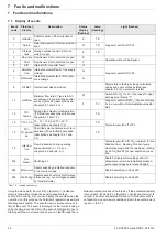
In the Solaris R4 regulator, the T

R

 light flashes.


Return temperature "T

R

" is greater than 40°C and is 10 K higher 

than the storage temperature "T

S

". The solar operating pump P

S


is switched off. The cause is a defective or incorrectly connected 
sensor. 

Ɣ

Install the sensor correctly or replace it; normal system
operation will be resumed.

In the status column of the Solaris R4 regulator, "W" flashes. 

The minimum flow rate start phase "V1" at the FlowSensor (see 
page 22, tab. 6-1) is not achieved after switching on the solar 
operating pump P

S

 and expiry of the time defined via the 

parameter [time P2] (fig. 6-3).

Î

The system goes to temporary blocking for 2 hours (solar 
operating pump P

S

 is switched off), but still tries to restart 

automatically after the blocking time.

Î

If this event occurs three times in a row, without interme-
diate starting, the solar operating pump P

S

 is switched off 

for an extended period and the status "F" is set.

In the status column of the Solaris R4 regulator, "F" flashes.


The minimum flow rate start phase "V1" at the FlowSensor (see 
page 22, tab. 6-1) is not achieved after switching on the solar 
operating pump P

S

 and expiry of the time defined via the 

parameter [time P2] (fig. 6-3). The solar operating pump P

S

 is 

switched off.

Ɣ

If a leak is suspected, examine the solar system, rectify faults
and then release the block by "Switching OFF/ON" on the 
controller.

If the system cannot be filled (

Status "F"

), even though the solar 

operating pump P

S

 is actuated by the regulator, the following 

faults can be the cause:

1. Air drawn down when the system was running idle is in the

solar operating pump P

S

.

Ɣ

Check that the solar operating pump P

S

 is running.

The automatic vent must always be working! Check the
sealing cap and loosen it if necessary (do not remove).

2. Check the installation for leaks.

Ɣ

Check the installation for leaks and rectify if necessary.
Follow instructions in section 5 "Start-up and decommis-
sioning"".

3. The start run time [time P2] (chap. 6.4).

4. Check the installation for blockage. In frosty conditions, ice

plugs can form in incorrectly run connecting pipes.

5. Check valve position on storage tank connection elbow.

If the 

display shows nothing

 and the main switch is in the illumi-

nated "ON position":

Ɣ

Replace the control unit (electronic fault).

If the main switch is not illuminated in the "On" position, there is 
no power supply to the control unit.

Ɣ

Check the plug connection of the mains plug and the mains
connection (fuse, switch).

If water vapour is continuously coming out

 of the solar 

storage tank 

when sunlight impinges

, the flow rate is too small.

Ɣ

In this case, the system settings must be checked.

Special notes on electric sensors

Ɣ

Evaluate the display of the Solaris R4 regulator.

Ɣ

Remove casing of the Solaris R4 regulator and remove and
disconnect the relevant sensors.

Ɣ

Examine the contact positions of the affected sensors, and
measure the resistance (or the DC voltage for flow temper-
ature and flow rate sensors) on the sensor end.

When the fault has been rectified, the system automatically re-
sumes normal operation and is in the operating mode.

The resistance or DC voltage values of the sensors are listed in 
fig. 9-1 and in fig. 9-2. Internal faults in the controller electronics 
that can be diagnosed are displayed in the display in accordance 
with tab. 7-1 (

Status "G"

). They also cause a safety switch-off of 

the pumps. Switching the system off and then on again after 
2 minutes might remedy the fault; if not, the control unit must be 
replaced.

CAUTION!

Danger of burning on hot surfaces.

Ɣ

Let the device cool down for a reasonably
long time before maintenance and inspection
work.

Ɣ

Wear protective gloves.

Only original ROTEX replacement parts may be used.

Summary of Contents for Rotex RPS4

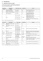
Page 1: ...ller ROTEX RPS4 Operating and installation instructions Regulation and pump unit for Solaris Solar Systems Valid for the following components ROTEX Solaris RPS4 Solaris R4 Differential temperature con...

Page 2: ...aris RPS4 04 2016 1 x Guarantee 1 Guarantee 1 1 Warranty conditions The legal guarantee conditions fundamentally apply Our war ranty conditions beyond that can be found online on your sales representa...

Page 3: ...Manual operation 21 6 2 7 FlowSensor 21 6 2 8 Output calculation maximum values and yield count 22 6 2 9 Speed regulation of the solar operating pump PS 22 6 2 10 Total Reset Function 23 6 2 11 Frost...

Page 4: ...documentation of the ROTEX solar system and therefore must be observed The documents are included in the scope of supply of the individual components ROTEX high performance flat solar panels Solaris...

Page 5: ...trained persons heating technicians roofers etc under observance of the relevant Accident Prevention Regulations Material and tools must be secured against falling Barriers must be erected to prevent...

Page 6: ...panel 10 Solar panel array 11 Solar flow line at the top on the solar panel 12 Thermal mixing valve scalding protection provided by customer 13 Convection brake accessory 14 Solar flow layering pipe 1...

Page 7: ...er heat pump Electronic control The fully electronic ROTEX Solaris R4 regulator ensures op timum utilisation of the solar heat hot water generation heating support and that all safety relevant aspects...

Page 8: ...adequate you can interconnect several Sanicube HybridCube as modules The following components are offered Solar storage tank extension kit CON SX 16 01 20 Solar storage tank kit 2 CON SXE 16 01 21 Flo...

Page 9: ...els can be mounted one above the other Solar panels or solar panel fields mounted one above the other must be connected in series fig 4 3 Fig 4 1 Solar panel field with a connection at each end recomm...

Page 10: ...regulations DANGER Leaking gas in the immediate proximity of electrical components can cause an explosion The RPS4 regulating and pump unit and electrical components should not be installed in locatio...

Page 11: ...of the FlowSensors c 4 Cut the flow pipe g 15 mm to the required length and insert it in the push in fitting f 5 Route the FlowSensor cable between the FlowSensor c and the Solaris R4 regulator 6 Plu...

Page 12: ...sensor and insert into the sensor tube 2 Position the return flow temperature sensor in the sensor tube at approx 130 cm insertion depth cable tie 3 Position the storage cylinder temperature sensor in...

Page 13: ...lti core with wire end sleeves with insulating collar 1 5 mm2 Multi core with wire end sleeves without insulating collar 2 5 mm2 Electrical connection 1 Plug in the supplied cables using the PCB edge...

Page 14: ...as shown in fig 4 28 and fig 4 29 point downwards 6 Cabling of the solar operating pump PS Connect the pump cable to the solar operating pump PS 7 Run the control cables along the return pipe and fix...

Page 15: ...control unit 2 Fix the cover to the control unit on both sides with countersunk screws 3 Fasten the cover to the cylinder connecting bracket underneath To do this carefully screw in the self tapping...

Page 16: ...distributed evenly to all the con nected solar storage tanks We recommend using a FlowGuard FLG at each storage tank for regulation pur poses 10 Instruct the user fill out the acceptance report and se...

Page 17: ...frost and may suffer damage Drain the heating system that is shut down if there is danger of frost CAUTION CAUTION Pumps that are switched off for a long time can seize With temporarily shut down sol...

Page 18: ...5 3 Fig 5 3 Assembling the KFE fill ing connection in the connecting angle Thanks to the environmentally friendly design of the solar system ROTEX has complied with requirements for environmentally so...

Page 19: ...r moving the temperature or pa rameter display up by one setting increas ing parameter settings 9 Down arrow for moving the temperature or parameter display down by one setting de creasing parameter s...

Page 20: ...ly switched off TS light flashes pump operation with activated intensified frost protection function star symbol flashes in the display see section 6 2 11 pump operation if the solar panel temperature...

Page 21: ...TV TR If the system has detected the FlowSensor once the display shows an error message if a sensor is faulty or is disconnected see section 7 1 Display of events The system then works in the emergen...

Page 22: ...ing pump PS then takes place between the determined minimum and maximum outputs The spread of TV and TR TV TR is measured continuously and compared with the target spread DT If the temperature spread...

Page 23: ...unction As soon as the Solaris R4 regulator detects a solar panel temper ature TK below 5 C non adjustable parameter T frost off the enhanced frost protection function becomes active This com pletely...

Page 24: ...tem perature 30 to 250 C 1 K TK min Min measured collector tem perature 30 to 250 C 1 K V max Maximum flow rate 0 0 to 12 0 l min 0 1 l min Maximum flow measured during filling 0 0 to 20 0 l min 0 0...

Page 25: ...he 3rd line burner block contact active see section 6 3 10 or a fault status see section 7 2 Trouble shooting H in the 4th line manual operating mode 6 3 3 Setup menu The Solaris R4 regulator paramete...

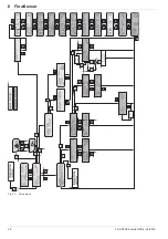
Page 26: ...26 FA ROTEX Solaris RPS4 04 2016 6 x FlowSensor Fig 6 7 Setup menu...

Page 27: ...h Enter choice 1 2 under Code 0000 It activates all important systems parameters in the settings menu for technicians see fig 6 7 6 3 5 Language selection During initial commissioning or after a total...

Page 28: ...ce P min or if the storage tank has heated up to the adjustable minimum storage tank temperature set by the heating expert operating pa rameter TS min see tab 6 5 the burner is deactivated via a conta...

Page 29: ...12 20 100 FLS 20 20 FLS 100 100 FR active Status frost protection function Yes No No H A Automatic return from manual to auto matic operation 1 to 900 min 30 min 1 min P min Min output for burner stop...

Page 30: ...em runs without evaporation in the collector However on a cloudless day this can lead to a situation where the system only switches on again in the late afternoon although the storage cylinder tempera...

Page 31: ...VBSK in such a way that the external heat generator does not heat see section 6 3 10 if a a minimum heating output is provided by the solar pan els or the storage cylinder has reached a sufficiently h...

Page 32: ...equipment fault of the supply voltage G 7 Reference Internal equipment fault of the refer ence voltage G 8 RESET Overall reset was carried out Parameters to factory settings calculated values and eve...

Page 33: ...ration is enabled automat ically Failures Sensor Cause of the fault Status blinks Display Lamp flashing Light flashes Collector temp Interruption K uuuu TK Long term switch off of PS Short circuit TK...

Page 34: ...aling cap and loosen it if necessary do not remove 2 Check the installation for leaks Check the installation for leaks and rectify if necessary Follow instructions in section 5 Start up and decommis s...

Page 35: ...atures up to 95 C If a heat exchanger is oper ated at temperatures greater than 95 C another gravity brake must be installed in the building A selection of diagrams of the most common installed syste...

Page 36: ...36 FA ROTEX Solaris RPS4 04 2016 8 x Hydraulic system connection Fig 8 2 Standard Solaris incorporation with GCU compact 1 Fig 8 3 Standard Solaris incorporation with Air Water Heat Pump HPSU compact1...

Page 37: ...laris RPS4 04 2016 37 1 The displayed plant schematics do not claim to be complete and do not replace careful indoor planning Fig 8 4 Standard Solaris incorporation with Air Water Heat Pump HPSU Bi Bl...

Page 38: ...ain regulator heat pump HPSU com pact HPSU compact series solar storage tank with integrated heat pump unit MAG Diaphragm expansion vessel MIX 3 way mixer with drive motor MK1 Mixer group with high ef...

Page 39: ...anel and the storage tank you cannot use the depressurised ROTEX solar system DrainBack and thus the regulation and pump unit RPS4 Instead the heating system can be executed with the ROTEX solar press...

Page 40: ...x D 230 x 815 x142 mm Operating voltage 230 V 50 Hz Solar operating pump Grundfos UPM3 15 145 Maximum electrical power consumptionRPS4 During start 65 W 115 W In normal mode 15 65 W modulated 30 115...

Page 41: ...characteristic curve RS Sensor resistance PTC Pt 1000 t Temperature Fig 9 1 Resistance characteristic lines of the Solaris sensor L Flow rate U Sensor output voltage t Temperature Fig 9 2 Characterist...

Page 42: ...42 FA ROTEX Solaris RPS4 04 2016 10 x Notes 10 Notes...

Page 43: ...n 20 29 34 Instantaneous output 35 M Malfunctions Manual 32 Rectification 33 Manual operation 6 21 22 23 25 27 28 Minimum pump output 22 23 Momentary output 24 Mounting position solar panel temperatur...

Page 44: ...ROTEX FA ROTEX Solaris RPS4 Subject to change and correction 008 1627444_01 04 2016...

Reviews: