background image

11

English

Facility Setting* 

(cooling at low outdoor temperature)

CAUTION

•  If the outdoor unit is installed where the heat exchanger of the unit is exposed to direct wind, provide a windbreak wall.
•  Intermittent noises may be produced by the indoor unit due to the outdoor fan turning on and off when using facility settings.
• 

Do not place humidifiers or other items which might raise the humidity in rooms where facility settings are being used. 


A humidifier might cause dew condensation from the indoor unit outlet vent.

•  Cutting jumper 6 (J6) sets the indoor fan tap to the highest position. Notify the user about this.

This function is limited only for facilities (the target of air conditioning is equipment (such as computer)). 

Never use it in a residence or office (the space where there is a human).

*Only for RX, RK, and RXL models.


„

Cutting jumper 6 (J6) on the circuit board will expand the operation range down to 5°F (–15°C). However it will stop if the 
outdoor temperature drops below –4°F (–20°C) and start back up once the temperature rises again.
1)  Remove the top plate of the outdoor unit. (09/12 class: 3 screws, 15/18/24 class: 6 screws)
2)  Remove the front plate. (09/12 class: 4 screws, 15/18/24 class: 8 screws)
3)  Cut the jumper (J6) of the PCB inside. 

Pump Down Operation

CAUTION

•  When pressing the switch, do not touch the terminal block. It has a high voltage, and touching it could cause electric shock.

In order to protect the environment, be sure to pump down when relocating or disposing of the unit. 

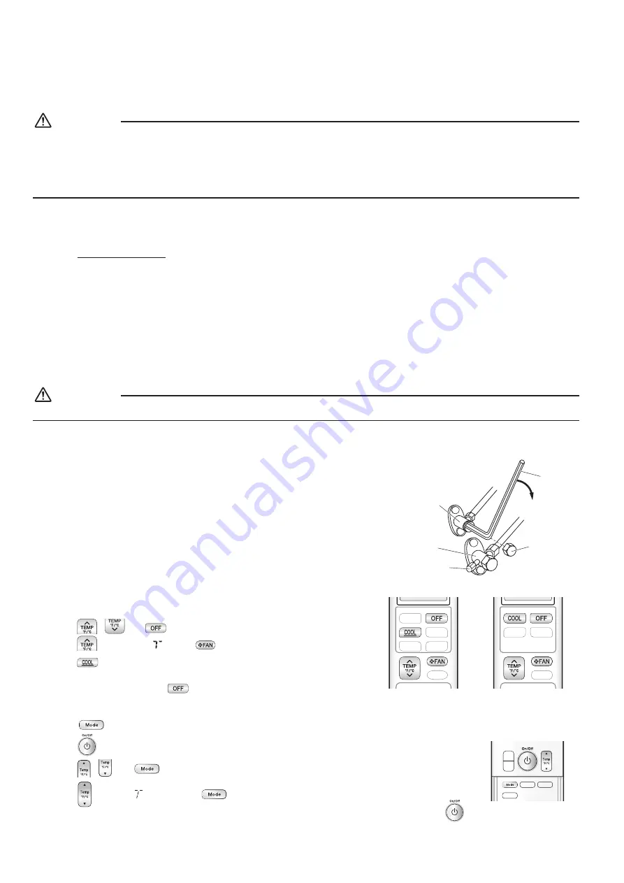
1) Remove the valve cap from the liquid stop valve and gas stop valve.
2) Begin forced cooling operation.
3) After 5 to 10 minutes, close the liquid stop valve with a hexagonal wrench.
4) After 2 to 3 minutes, close the gas stop valve and stop forced cooling operation.
5) Attach the valve cap once procedures are complete.

Forced cooling operation


„

Using the indoor unit ON/OFF switch 
Press the indoor unit ON/OFF switch for at least 5 seconds. (The operation will start.) 

•  Forced cooling operation will stop automatically after about 15 minutes. 

To stop the operation, press the indoor unit ON/OFF switch.

Gas 
stop valve

Valve cap

Hexagonal 
wrench

Close

Liquid 
stop valve

Service port


„

Using the indoor unit’s remote controller
[For wall mounted units]

1) Press 

 , 

 and 

 at the same time.

2) Press 

 , then select   , press 

 .

3) Press 

 to turn on the system.

•  Forced cooling operation will stop automatically after about 30 minutes. 

To stop the operation, press 

HEAT PUMP model

COOLING ONLY model

[For floor standing units]

1) Press 

 and select the COOL operation.

2) Press 

 to turn on the system.

3) Press 

 , 

 and 

 at the same time. 

4) Press 

 , select “ 

 ”, and press 

 for confirmation.

•  Forced cooling operation will stop automatically after about 30 minutes. To stop the operation, press 

 .

01_EN_3P572321-3.indd   11

2019/06/19   14:17:28

Summary of Contents for RK09NMVJU

Page 1: ...18NMVJU RXN24NMVJU RK09NMVJU RK12NMVJU RK18NMVJU RK24NMVJU RKN09NMVJU RKN12NMVJU RKN18NMVJU RKN24NMVJU RXL09QMVJU RXL12QMVJU RXL12QMVJU9 RXL15QMVJU DAIKIN ROOM AIR CONDITIONER INSTALLATION MANUAL R410A Split Series Installation manual Manuel dinstallation Manual de instalación Manuel dinstallation ...

Page 2: ...hyxiation hazard could occur leading to serious injury or death Do not ground units to water pipes gas pipes telephone wires or lightning rods as incomplete grounding can cause a severe shock hazard resulting in severe injury or death Additionally grounding to gas pipes could cause a gas leak and potential explosion causing severe injury or death If refrigerant gas leaks during installation ventil...

Page 3: ...m getting into the system b Tight R410A does not contain any chlorine does not destroy the ozone layer and does not reduce the earth s protection again harmful ultraviolet radiation R410A can contribute to the greenhouse effect if it is released Therefore take proper measures to check for the tightness of the refrigerant piping installation Read the chapter Refrigerant Piping Work and follow the p...

Page 4: ...containing sulfate gas corrosion may shorten the life of the air conditioner 8 Since water will flow from the drain of the outdoor unit do not place under the unit anything which must be kept away from moisture NOTE Cannot be installed suspended from a ceiling or stacked CAUTION When operating the air conditioner in a low outdoor ambient temperature be sure to follow the instructions described bel...

Page 5: ...vibration may occur depending on how the unit is installed and the environment in which it is used 10ft 3m O D 1 2 inch 12 7mm O D 5 8 inch 15 9mm RX18 RXN18 RK18 RKN18 RXL15 RX24 RXN24 RK24 RKN24 RX09 12 RK09 12 RXL09 12 RXN09 12 RKN09 12 65 5 8ft 20m 98 1 2ft 30m Min allowable piping length X Foot bolt hole centers From unit s side Z Footbolt hole centers Y Allow 11 13 16 300mm of work space bel...

Page 6: ...ing one side More than 1 15 16 50 More than 1 15 16 50 Top view More than 3 15 16 100 Walls facing two sides More than 13 3 4 350 09 12 class 15 18 24 class When installed as in the figure on the left it is recommended to either change the orientation of the outdoor unit outlet side or use the air direction adjustment grille sold separately More than 3 15 16 100 More than 13 3 4 150 When installed ...

Page 7: ...with the cut surface facing downward so that the filings do not enter the pipe 3 Put the flare nut on the pipe 4 Flare the pipe 5 Check that the flaring has been done correctly Check The flare s inner surface must be flaw free When flaring do not over tighten and crack The pipe end must be evenly flared in a perfect circle Make sure that the flare nut is fitted Set exactly at the position shown below Fl...

Page 8: ...ns as below Gas side Piping size O D 3 8 inch 9 5mm O D 1 2 inch 12 7mm O D 5 8 inch 15 9mm O D 1 4 inch 6 4mm 1 3 16 inch 30mm or more 1 9 16 inch 40mm or more 1 15 16 inch 50mm or more 1 3 16 inch 30mm or more 0 031 inch 0 8mm C1220T O 0 039 inch 1 0mm C1220T O 0 031 inch 0 8mm C1220T O I D 15 32 19 32 inch 12 15mm I D 9 16 5 8 inch 14 16mm I D 5 8 13 16 inch 16 20mm I D 5 16 13 32 inch 8 10mm 1...

Page 9: ...alve 7 To open the liquid stop valve turn the rod of the valve 90 counter clockwise using a hexagonal wrench Close it after 5 seconds and check for gas leakage Using soapy water check for gas leakage from the indoor unit s flare and outdoor unit s flare and valve rods After the check is complete wipe all soapy water off 8 Disconnect the charging hoses from the service port for the gas stop valve t...

Page 10: ... A A When connecting the inter unit wires to the terminal block using a single core wire be sure to curl the end of the lead Improper work may cause heat and fire Strip wire end to this point Excessive strip length may cause electric shock or current leakage Stripping wire at terminal block Good Wrong Good Wrong Do not turn on the circuit breaker until all work is completed 1 Strip the insulation ...

Page 11: ...its original position 1 2 3 1 2 3 1 2 3 Screws Conduit mounting cover Screws Protection plate Power supply terminal block Shape wires so that the protection plate and conduit mounting plate fit securely Conduit Lock nut Conduit mounting plate L1 L2 15 18 24 class Method of mounting conduit 1 Dismount the service lid by removing the 2 screws 2 Pass wires through the conduit and secure them with a lo...

Page 12: ...CAUTION When pressing the switch do not touch the terminal block It has a high voltage and touching it could cause electric shock In order to protect the environment be sure to pump down when relocating or disposing of the unit 1 Remove the valve cap from the liquid stop valve and gas stop valve 2 Begin forced cooling operation 3 After 5 to 10 minutes close the liquid stop valve with a hexagonal w...

Page 13: ... temperature 80 F Cool Test Operation Press the On Off button within 10 seconds For wireless remote controller 1 Press and select the COOL operation 2 Press twice Test is displayed 3 Press within 10 seconds and the forced cooling operation starts Forced cooling operation will stop automatically after about 15 minutes To stop the operation press Trial Operation and Testing 1 Trial operation and tes...

Page 14: ...Two dimensional bar code is a manufacturing code 3P572321 3 M18B313 1907 HT ...

Reviews: