background image

18

3P362438-3H English

8 .3 .2 .  How to use the stop valve
Tightening torques

Stop 

valve 

size

Tightening torque (Turn clockwise to close)

Shaft (valve body)

Cap

(valve cover)

Service 

port

f

3/8

3.98-4.87 ft

lbf

(5.4-6.6 N

m)

Hexagonal 

wrench 

4 mm

9.95-12.17 ft

lbf

(13.5-16.5 N

m)

8.48-10.3 

ft

lbf

(11.5-13.9 

N

m)

f

1/2

5.97-7.30 ft

lbf

(8.1-9.9 N

m)

13.3-16.2 ft

lbf

(18.0-22.0 N

m)

f

3/4

19.9-24.3 ft

lbf

(27.0-33.0 N

m)

Hexagonal 

wrench

8 mm

16.6-20.3 ft

lbf

(22.5-27.5 N

m)

f

1

f

1-1/8

Hexagonal 

wrench

10 mm

Opening the stop valve

Remove the stop valve cover.

Insert a hexagon wrench into the stop valve and turn the stop valve 

counterclockwise.

When the stop valve cannot be turned any further, stop turning.
The valve is now open.

• 

Turn the stop valve (

f

3/8, 

f

1/2) until the shaft stops.  

(Opening the valve with excessive force may damage it.)

• 

Turn the stop valve (

f

3/4 - 

f

1-1/8) until the shaft stops and the 

designated torque is achieved.

Tighten the stop valve cover securely by applying the designated 
torque.

1

2

3

4

Closing the stop valve

Remove the stop valve cover.

Insert a hexagon wrench into the stop valve and turn the stop valve 

clockwise.

Turn until the shaft stops by applying the designated torque.  
The valve is now closed.

Tighten the stop valve cover securely by applying the designated 
torque.

Closing direction

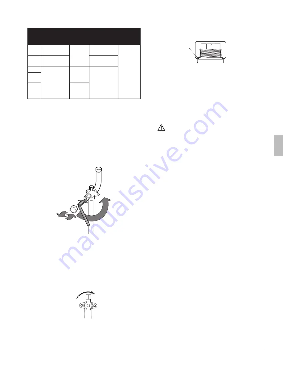
8 .3 .3 .  Cautions on handling the stop valve cover

• 

The stop valve cover is sealed where indicated by the arrow. Take 
care not to damage it.

• 

After handling the stop valve, make sure to tighten the stop valve 
cover securely. For the tightening torque, refer to 8.3.2. How to use 
the stop valve.

• 

Check for refrigerant leaks after tightening the stop valve cover.

8 .3 .4 .  Cautions on handling the service port

• 

Always use a charge hose equipped with a valve depressor pin, 
since the service port is a Schrader type valve.

• 

After handling the service port, make sure to tighten the service 
port cover securely. For the tightening torque, refer to 8.3.2. How to 
use the stop valve.

• 

Check for refrigerant leaks after tightening the service port cover.

9 .  Field wiring

 NOTE

•  All field wiring and components must be installed by a licensed elec

-

trician and must comply with relevant local and national regulations.

• 

Be sure to use a dedicated power circuit. Never use a power supply 
shared by another appliance.

• 

Never install a phase-advancing capacitor. As this unit is equipped 
with an inverter, installing a phase-advancing capacitor will not only 
deteriorate power factor improvement effect, but also may cause 
capacitor abnormal heating accident due to high-frequency waves.

• 

Only proceed with wiring work after blocking off all power.

• 

Always ground wires in accordance with relevant local and national 
regulations.

• 

This machine includes an inverter device. Connect ground and 
leave charge to eliminate the impact on other devices by reducing 
noise generated from the inverter device and to prevent leaked cur-
rent from being charged in the outer shell of the product.

• 

Do not connect the ground wire to gas pipes, sewage pipes, light-
ning rods, or telephone ground wires.

Gas pipes

 can explode or catch fire if there is a gas leak.

Sewage pipes:

 no grounding effect is possible if hard plastic piping 

is used.

Telephone ground wires and lightning rods 

are dangerous when 

struck by lightning due to abnormal rise in electrical potential in the 
grounding.

• 

This equipment can be installed with a Ground-Fault Circuit Inter-
rupter (GFCI). Although this is a recognized measure for additional 
protection, with the grounding system in North America, a dedi-
cated GFCI is not necessary.

•  Electrical wiring must be done in accordance with the wiring dia

-

grams and the description herein.

• 

Do not operate until refrigerant piping work is completed. Operating the 
unit before completing piping work could cause the compressor to break.

• 

Never remove a thermistor, sensor or similar parts when connecting 
power wiring and transmission wiring. 
(If operated with a thermistor, sensor or similar parts removed, the 
compressor may be broken down.)

• 

Never connect the power supply in reverse-phase.
The unit cannot operate normally in reverse-phase.
If you connect in reverse-phase, replace 2 of the 3 phases.

•  Make sure the electrical imbalance ratio is no greater than 2%. If it is 

larger than this, the unit’s lifespan will be reduced.

If the ratio exceeds 4%, the unit will shut down and an malfunction 

code will be displayed on the indoor remote controller.

01_EN_3P362438-3H.indb   18

1/14/2015   10:19:40 AM

Summary of Contents for REYQ72TTJU

Page 1: ...REYQ264TTJU REYQ288TTJU REYQ312TTJU REYQ336TTJU REYQ360TTJU REYQ384TTJU REYQ408TTJU REYQ432TTJU REYQ456TTJU REYQ72TYDN REYQ96TYDN REYQ120TYDN REYQ144TYDN REYQ168TYDN REYQ192TYDN REYQ216TYDN REYQ240TYD...

Page 2: ...ING Only qualified personnel must carry out the installation work Installation must be done in accordance with this installation manual Improper installation could result in water leakage electric sho...

Page 3: ...away from fluorescent lamps as much as possible Indoor units are for indoor installation only Outdoor units can be installed either outdoors or indoors This unit is for indoor use Do not install the a...

Page 4: ...ize 9 7 4 Selection of refrigerant branch kits 10 7 5 System piping length limitations 11 8 Precautions on refrigerant piping 14 8 1 Caution for brazing 14 8 2 Connecting the refrigerant piping 14 8 3...

Page 5: ...1 REYQ120TTJU TYDN 1 REYQ144TTJU TYDN 1 72 96 120 144 168 REYQ168TTJU TYDN 1 REYQ192TTJU TYDN 1 1 REYQ216TTJU TYDN 1 1 REYQ240TTJU TYDN 1 1 REYQ264TTJU TYDN 1 1 REYQ288TTJU TYDN 2 REYQ312TTJU TYDN 1...

Page 6: ...accessories is shown in the figure below Accessories assy piping Accessories assy operation and installation manual NOTE Do not throw away any of the accessories until installation is complete They ar...

Page 7: ...e reasonable protection against such interference However there is no guarantee that inter ference will not occur in a particular installation It is therefore recommended to install the equipment and...

Page 8: ...nopy 2 Construct a pedestal NOTE When operating the unit in a low outdoor ambient temperature with high humidity conditions make sure to take precautions to keep the drainholes of the unit free by usi...

Page 9: ...a Front side Suction side b h2 2 or more Service space h1 2 or more h1 b a 59 in 1500 mm b 19 5 8 in 500 mm In case of an installation site where sides A B C D have obsta cles the wall heights of sid...

Page 10: ...y attention to the position of the unit s center of gravity NOTE Use a belt sling of 3 4 in 20 mm wide that adequately bears the weight of the unit A forklift can only be used for transport as long as...

Page 11: ...0 mm above the foundation surface A A 13 16 in 20 mm NOTE There are restrictions on the refrigerant pipe connecting order between outdoor unit in the case of the multi system See 1 2 2 Outdoor unit co...

Page 12: ...r other contamination Foreign materials inside pipes including oils for fabrication must be 0 14 gr 10 ft 30 mg 10 m or less Use the following items for the refrigerant piping Material Jointless phosp...

Page 13: ...e on page 9 When using REFNET joints at the first branch from the outdoor unit choose from the following table in accordance with the capacity of the outdoor unit example REFNET joint a see 7 3 Select...

Page 14: ...i connection piping kit must always be installed horizontally paying attention to the installation restrictions indicated in 8 Precautions on refrigerant piping Example of connection 8 indoor units ar...

Page 15: ...t 40 m From indoor unit to indoor unit Height difference From outdoor unit to outdoor unit Height difference Height difference between outdoor units H3 16 ft 5 m Allowable length after branch 3 Actual...

Page 16: ...8 A G p Indoor unit 1 8 j k BS BS BS BS BS BS BS 2 s r q b c d e f g p 130 ft 40 m From outdoor unit to the farthest indoor unit 9 From outdoor unit to the nearest indoor unit 1 2 The total piping len...

Page 17: ...gh with Dry Nitrogen prevents the creation of large quantities of oxidized film on the inside of the piping An oxidized film ad versely affects valves and compressors in the refrigerating system and p...

Page 18: ...cting with the burner flame Liquid pipe stop valve Suction gas pipe stop value Protective plate Stop valve mounting plate High Low pressure gas pipe stop valve 5 Cut off the lower part of the smaller...

Page 19: ...ions to the branch kits are the responsibility of the installer field piping 8 2 4 Precautions when connecting piping between outdoor units multiple outdoor unit system To connect the piping between o...

Page 20: ...branches either horizontally or vertically Mount the REFNET header so that it branches horizontally 2 Installation of the multi connection piping kit A 1 B 1 C D 15 C 4 3 4 in 120 mm D 19 11 16 in 50...

Page 21: ...installed by a licensed elec trician and must comply with relevant local and national regulations Be sure to use a dedicated power circuit Never use a power supply shared by another appliance Never in...

Page 22: ...61 9A 61 9A 43 0A 43 0A 43 0A 38 0A 43 0A 61 9A 38 0A 55 0A 61 9A 55 0A 55 0A 55 0A 55 0A 55 0A 61 9A 15 2A 21 1A 21 1A 31 9A 36 1A 15 2A 21 1A 21 1A 21 1A 21 1A 31 9A 21 1A 31 9A 31 9A 31 9A 31 9A 3...

Page 23: ...11 BS unit 12 Indoor unit 13 Indoor unit Cooling only The Outdoor unit that connect the transmission wiring to BS unit is Master unit of the multi system And the other units are Sub unit In this figur...

Page 24: ...230 V 60 Hz 2 Branch switch Overcurrent breaker 3 Ground wire 4 Control box 5 Only REYQ TYDN Control box 2 6 Only REYQ TYDN Do not open the control box 2 cover There are no work when installation 7 At...

Page 25: ...connect it using a conduit Choose an appropriate knockout hole for conduit size suitable for the power and ground line to be used Transmission line Connect it using a conduit in the knockout hole on t...

Page 26: ...uge rises or not If it rises the system may either contain moisture inside or have leaks NOTE During the rainy season moisture might enter the piping If working during a rainy season and the work take...

Page 27: ...To access you can remove the front inspection door of the front panel see figure Now you can open the inspection door of the control box front panel see figure You can see 3 push buttons and 3 seven s...

Page 28: ...situation is the amount of indoor units which are con nected to the system Result mode 1 setting 10 is addressed and selected return value is monitored information To leave the monitoring function pus...

Page 29: ...efriger ant charge In case recharge is required refer to the nameplate of the unit It states the type of refrigerant and necessary amount 14 2 Calculating the additional refrigerant charge NOTE The re...

Page 30: ...REYQ120TTJU BS units BS4Q54T 1 BSQ60T 1 BSQ96T 1 Indoor units FXMQ type 18 1 24 2 36 1 54 1 FXFQ type 36 2 Other 48 1 Liquid piping a f3 4 60 ft e f1 4 15 ft i f3 8 20 ft m f3 8 20 ft r f1 2 10 ft b f...

Page 31: ...r refrigerant to reach R Q Step 4b Close valve B R Q Step 5 Open all outdoor unit stop valves Step 6 Proceed with automatic or manual charge A Automatic charge B Manual charge Step 6a Push BS2 once 88...

Page 32: ...des appear E 2 indoor temperature out of range and E 3 outdoor temperature out of range In this case perform automatic charging procedure again See figure Location of valves next page for more informa...

Page 33: ...ns to be taken see 14 3 1 Flow chart on page 28 To speed up the process of pre charging refrigerant for large systems it is recommended to first charge a portion of the refrigerant before performing a...

Page 34: ...he unit indicates E 2 or E 3 the ambient conditions are NOT favorable to execute the test run Push BS1 to finish the automatic charging procedure INFORMATION In case a malfunction code occurred during...

Page 35: ...ing for each outdoor unit and calculate the average subcooling of the outdoor unit Systems should have a subcooling of 11 3 F 6 2 C a If average subcooling is low add charge to raise subcooling to 11...

Page 36: ...nominal operating conditions Low noise operation can be set in mode 2 There are two methods to activate low noise operation of the outdoor unit system The first method is to enable an automatic low n...

Page 37: ...onsumption limitation conditions when an external signal is sent to the unit this setting should be changed This setting will only be effective when the optional external control adaptor DTA104A61 62...

Page 38: ...efines the level power consumption limitation that will be applied continuously The level is according to the table Default value 0 OFF Value 2 32 Restriction reference 0 Function not active default 1...

Page 39: ...ing is used in conjunction with setting 2 9 For more information and advice about the impact of these settings see 15 3 Energy saving and optimum operation 15 3 Energy saving and optimum operation Thi...

Page 40: ...ion or undershoot during cooling operation is allowed compared to the requested refrigerant tem perature in order to achieve the required room temperature very fast The overshoot is allowed from the s...

Page 41: ...erature evolution A B C D E F A Indoor unit set temperature B Operation start C Operating time D Mild E Quick F Powerful Example Automatic mode during cooling A B 100 70 E Tc C D 120 F 49 C F 115 F 46...

Page 42: ...sts stand by periods etc INFORMATION Note that during the first running period of the unit required power in put may be higher This phenomenon originates from the compressor that requires a 50 hour ru...

Page 43: ...ting the abnormality press BS3 to reset the malfunction code and retry operation The malfunction code which is displayed on the outdoor unit will indi cate a main malfunction code and a sub code The s...

Page 44: ...r malfunction R14T A1P X19A Check connection on printed circuit board or actuator J5 01 03 05 Temperature sensor malfunction R12T A8P X15A Check connection on printed circuit board or actuator 18 19 2...

Page 45: ...V1 voltage power shortage or open phase Check if power supply is within range Correct phase order 02 09 12 INV1 reversed or open power supply phase Check if power supply is within range Correct phase...

Page 46: ...3P362438 3H EM14A006B 1502 HT...

Reviews: