background image

EDUS39-605

Installation

Installation of Outdoor Units

50

7.

Leak test and vacuum drying

Ensure units were checked for leaks by the manufacturer.

Confirm that the valves are firmly closed before pressure test
or vacuuming.

To prevent entry of any impurities and  to ensure sufficient 
pressure resistance, always use the specific tools  for R-410A.

Air tight test and vacuum drying

Air tight test: Make sure to use nitrogen gas.
For the service port location, refer to the

[CAUTION]

 label attached on the right

front panel of the outdoor unit.

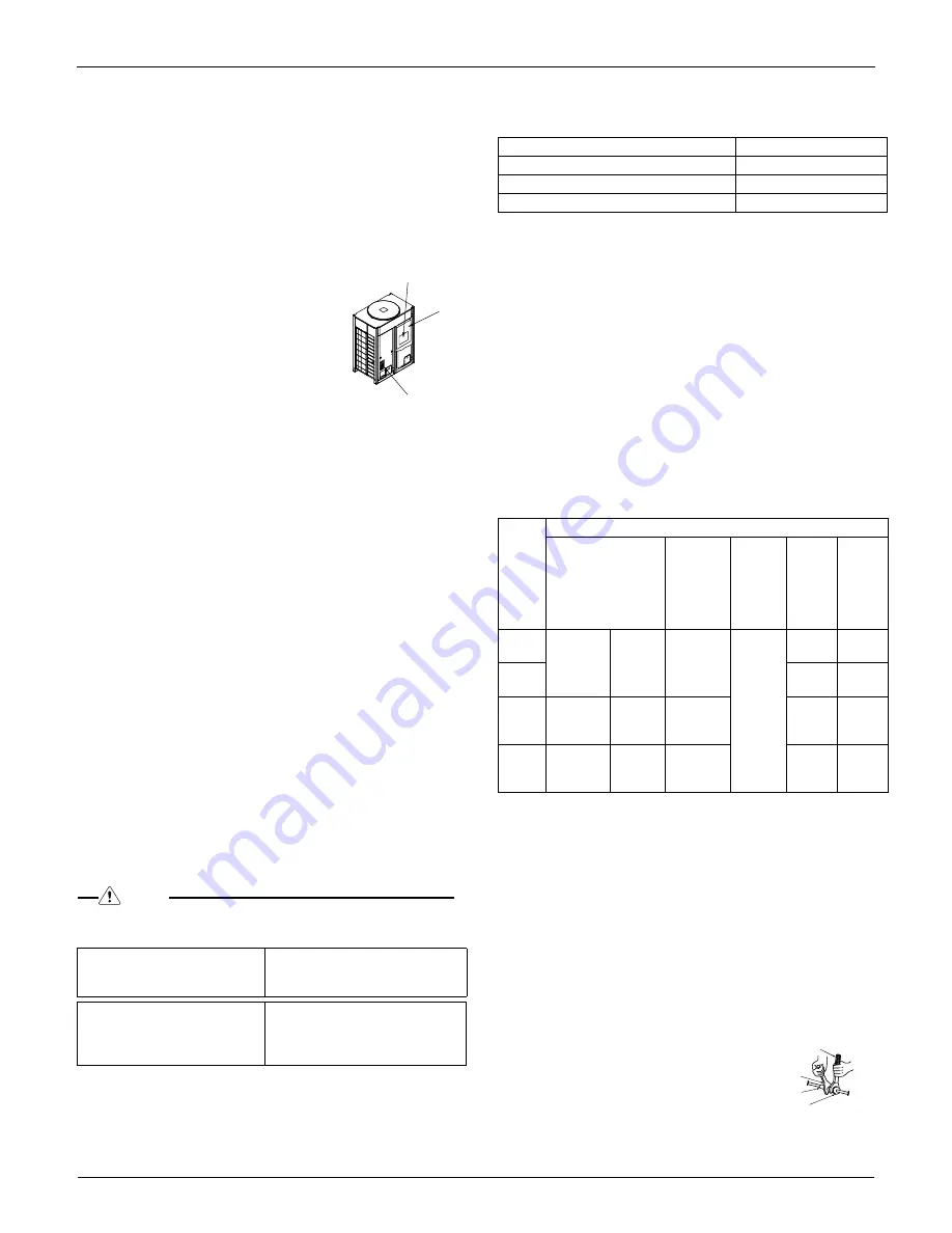
Refer to figure to right:

1.

[

Service precautions

]

Label location

2.

Electric parts box lid

3.

[

Caution

]

Label location

Pressurize the liquid, suction gas, and discharge gas pipes 
to 551 psi (do not pressurize more than 551 psi). If the 
pressure does not drop within 24 hours, the system passes 
the test. If the pressure drops

check where the nitrogen 

leaks from.

Vacuum drying: Use a vacuum pump  that can evacuate to 
–14.6 psi.

1.

Evacuate the system from the liquid, suction gas, and 
discharge gas pipes by using a vacuum pump for more 
than 2 hours and bring the system to –14.6 psi. After 
keeping the system under that condition for more than 1 
hour, check if the vacuum gauge rises or not. If it rises, 
the system may either contain moisture inside or have 
leaks.

2.

 if piping work is carried out during the  rainy season or 
over a long period of time, rainwater may enter the pipe 
during work. Any possibility of moisture remaining inside 
the pipe requires the following action:
After evacuating the system for 2 hours, pressurize the 
system to 7.25psi (vacuum break) with nitrogen gas and 
evacuate the system again using the vacuum pump for 1 
hour to –14.6 psi (vacuum drying). If the system cannot 
be evacuated to –14.6 psi within 2 hours, repeat the 
operation of vacuum break and vacuum drying.
 After leaving the system in vacuum for 1 hour, confirm 
that the vacuum gauge does not rise.

NOTE

Make sure to perform air-tight test and vacuum drying using the ser-
vice ports of the stop valve shown in the table below.

Stop valve operation procedure:

Confirm the sizes of the stop valves connected to the system referring
to the following table: 


Opening the stop valve:

1.

Remove the cap and turn the valve counterclockwise with
the hexagon wrench.

2.

Turn it until the shaft stops.
Do not apply excessive force to the stop valve. Doing so
may break the valve body, as the valve is not a backseat
type. Always use the special tool.

3.

Make sure to tighten the cap securely.

Closing stop valve:

1.

Remove the cap and turn the valve clockwise with the
hexagon wrench.

2.

Securely tighten the valve until the shaft contacts the main
body seal.

3.

Make sure to tighten the cap securely.

Tightening torque: 

(Refer to figure 22 page 39)

1.

Service port

2.

Cap

3.

Hexagon hole

4.

Shaft

5.

Seal

CAUTION:

Always use a charge hose for service port connection.

After tightening the cap, check that no refrigerant leaks are
present.

When loosening a flare nut, always use two wrenches in
combination. When connecting the piping, always use a
spanner and torque wrench in combination to tighten the
flare nut.

When connecting a flare nut, 
coat the flare (inner and outer 
faces) with ether oil or ester oil 
and handtighten the nut 3 to 4 
turns initially.  

One outdoor unit installed

Liquid line stop valve
Discharge gas line stop valve
Suction gas line stop valve

Multiple outdoor units installed

Liquid line stop valve
Discharge gas line stop valve
Suction gas line stop valve
Oil-equalizing line stop valve

1

3

2

Q96 type

Liquid line stop valve

φ 

3/8”

Suction gas line stop valve

φ 

7/8”

Discharge gas line stop valve

φ 

3/4”

Stop 

valve 

size

Tightening torque ft.-Ibf (Turn clockwise to close)

Shaft (valve body)

Cap 

(valve lid)

Service 

port

Flare nut

Suction 

gas line 

piping 

attached 

to unit 

(1)

1/4”

3.98-4.87

Hexagon 
wrench
4 mm

9.96-12.17

8.48-

10.25

10.3-

12.5

3/8”

24.1-

29.4

3/4”

9.96-12.17

Hexagon 
wrench
6mm

17.33-

20.28

71.6-

87.8

7/8”

19.91-

24.34

Hexagon 
wrench
10mm

26.55-

32.45

16.23-

20.65

Torque wrench

Spanner

Piping union

Flare nut

Summary of Contents for REYQ72/96MTJU

Page 1: ......

Page 2: ...NET Pipe System 3 3 1 Layout Example 3 3 2 Field Refrigerant Piping 5 3 3 REFNET Joints and Headers 6 4 REFNET Pipe System 8 4 1 REFNET Joint Branch Kit 8 4 2 REFNET Header Branch Kit 10 4 3 Outdoor U...

Page 3: ...Center of Gravity EDUS39 605 2 Installation of Outdoor Units 1 Center of Gravity RXYQ72 96MTJU REYQ72 96MTJU 4D045330...

Page 4: ...EDUS39 605 Foundation Drawing Installation of Outdoor Units 3 2 Foundation Drawing RXYQ72 96MTJU REYQ72 96MTJU 3D042653A...

Page 5: ...ded in the system downsteam of a REFNET header Notes 1 When the capacity ratio of the indoor system to the outdoor unit is more than 100 and when all the indoor units are in operation at the same time...

Page 6: ...nnot be included in the system below the REFNET header branch Notes 1 When the capacity ratio of the indoor system to the outdoor unit is more than 100 and when all the indoor units are in operation a...

Page 7: ...s and liquid piping must be insulated Materials Glass fiber or heat resistant polyethylene foam Thickness 1 2 inch or more Heat resistance Gas pipe 250 F or more Liquid pipe 160 F or more 3 2 2 Heat R...

Page 8: ...or vertically When the size of the selected field piping is different from that of the branch pipe the connecting section should be cut with a pipe cutter as shown in the figure below When cutting an...

Page 9: ...on the outdoor unit side of the liquid pipe header cut the B section with a pipe cutter and connect it to the A section Connect the flared section of the field pipe to the B section as shown in the fo...

Page 10: ...nsulation unit in Liquid Side D3K03622C 1 2 4 3 4 5 8 1 2 7 8 3 4 5 8 5 8 1 2 5 8 3 4 3 1 1 2 15 13 1 3 3 3 3 8 3 8 1 4 3 8 1 4 1 1 2 9 7 8 11 1 2 Gas Side Insulation Insulation Liquid Side D3K03623A...

Page 11: ...5 8 3 8 3 8 3 8 3 8 3 8 3 8 1 4 1 4 3 3 3 3 12 13 1 3 1 1 2 1 1 2 1 1 2 13 1 3 12 2 1 3 D3K03627B Suction gas side Discharge gas side Liquid side Insulation Insulation Insulation 7 8 7 8 7 8 3 4 3 4 3...

Page 12: ...30C Gas Side Liquid Side Insulation Insulation 4 3 4 5 8 3 4 5 8 5 8 5 8 1 2 5 8 1 2 1 2 1 2 7 8 1 0 3 8 24 1 4 10 1 2 10 1 2 5 3 4 2 x 2 1 2 5 4 3 4 4 3 4 4 3 4 4 3 4 6 3 4 7 8 3 1 5 6 6 20 3 8 3 8 1...

Page 13: ...1 2 17 1 2 3 1 5 4 3 4 6 3 4 3 3 8 3 8 1 2 1 4 1 4 1 4 3 8 20 1 1 2 6 26 1 3 2 1 2 2 1 2 3 3 4 3 5 x 2 1 2 10 1 2 D3K03634C 27 Suction gas side Discharge gas side Insulation Insulation Insulation Liqu...

Page 14: ...EDUS39 605 REFNET Pipe System Installation of Outdoor Units 13 4 3 Outdoor Unit Multi Connection Piping Kit BHFP26M90U...

Page 15: ...REFNET Pipe System EDUS39 605 14 Installation...

Page 16: ...EDUS39 605 REFNET Pipe System Installation of Outdoor Units 15 BHFP26M90U To indoor unit 3D050301 3D050302 3D050303...

Page 17: ...H1 59 X H2 19 5 8 H2 19 5 8 Y A 19 5 8 A 19 5 8 X 2 B1 11 3 4 B2 3 7 8 B1 11 3 4 Y 2 B2 3 7 8 Y 2 figure 1 60 5 3 1 4 2 2 in 40 4 0 40 60 60 60 figure 2 6 3 5 7 3 4 1 2 8 in 28 7 16 29 2 5 8 2 5 8 30...

Page 18: ...2 Multiple outdoor units installed One outdoor unit installed 1 6 5 4 3 2 figure 11 1 2 3 4 5 6 7 8 9 10 11 12 17 13 1 2 3 4 5 6 7 13 12 14 9 8 9 10 15 17 16 One outdoor unit installed Multiple outdoo...

Page 19: ...ECTOR TO IN D UNIT TO OUT D UNIT TO MULTI UNIT A1P 3 figure 15 figure 16 A B C F1 F2 F1 F2 Q1 Q2 Q1 Q2 A1P 1 3 6 7 8 4 5 5 2 figure 17 TO IN D UNIT F1 F2 DS1 1 2 3 4 OFF ON O U T I N F1 F2 P1 P2 P1 P2...

Page 20: ...plastic packaging bags so that children cannot play with them Before touching electrical parts turn off the unit Se curely install the outdoor unit terminal cover panel If the terminal cover panel is...

Page 21: ...ficient power supply capacity or improper electri cal construction may lead to electric shocks or fire Make sure that all wiring is secured the specified wires are used and no external forces act on t...

Page 22: ...on Manual Additional refrigerant Charge label Shape REFNET header KHRP26M22H KHRP26M33H KHRP26M72H REFNET joint KHRP26M22T KHRP26M33T KHRP26M72TU Number of outdoor units connected 2 units Kit name BHF...

Page 23: ...unit 2 Branch switch overcurrent breaker 3 remote controller 4 COOL HEAT selector 5 personal computer or radio If the electric wave of AM broadcasting is particularly strong keep distances of 10 ft o...

Page 24: ...ate waste water from the unit 2 If the unit is to be installed on a roof check the strength of the roof and its drainage facilities before beginning installation 3 If the unit is to be installed on a...

Page 25: ...ng flourine damages refrigerant oil 6 1 Selection of piping material 1 Foreign materials inside pipes including oils for fabrica tion must be 30mg 10m or less 2 Use the following material specificatio...

Page 26: ...95 ISO 3677 which does not require flux Flux has an extremely negative effect on refrigerant piping systems For instance if chlorine based flux is used it will cause pipe corrosion Flux containing flo...

Page 27: ...agram Pattern 1 Pattern 2 Prohibited pattern Change to pattern 1 or pattern 2 to indoor unit Piping between outdoor units Piping between outdoor units to indoor unit to indoor unit to indoor unit to i...

Page 28: ...sen by general system model name How to calculate the additional refrigerant to be charged If a negative result is gotten for R from the formula at right no refrigerant needs to be added Additional re...

Page 29: ...ction Confirm the sizes of the stop valves connected to the system referring to the table on the below Opening the stop valve 1 Remove the cap and turn the valve counterclockwise with the hexagon wren...

Page 30: ...nto the indoor unit through gaps in the insulation and piping because the outdoor unit is located higher than the indoor unit etc this must be pre vented by corking the connections etc Refer to figure...

Page 31: ...d properly if the stop valve is not correct Multiple Outdoor Units Installed Refer to figure 12 To learn the system settings for additional refrigerant charg ing refer to theService Precaution label a...

Page 32: ...generates noise which must be reduced to avoid interfering with other devices The outer casing of the product may take on an electrical charge due to leaked electrical current which then must be disc...

Page 33: ...round connection may prevent a good ground from being achieved WARNING Use only specified wire and connect wires to terminals tightly Be careful that wires do not place external stress on terminals Ke...

Page 34: ...ch other keep ing them at least 50 mm apart Proximity may cause electrical interference malfunctions and breakage Be sure to connect the power wiring to the power wiring terminal block and secure it a...

Page 35: ...ng an operation always verify that the LED display shows the contents of the table in Section 8 2 Test Operation The system may require up to 10 minutes until it can start the compressor after an oper...

Page 36: ...s installed in a large enough room to ensure that the maximum concentra tion level of refrigerant gas is not exceeded This is a safe guard in the unlikely event of a major leak and complies with local...

Page 37: ...rtition Where there is an opening without a door or where there are openings above and below the door which are each equivalent in size to 0 15 or more of the floor area 2 Calculating the refrigerant...

Page 38: ...2 Pattern 3 Pattern 1 Pattern 2 Pattern 3 When installed in serial 1 1 2 2 1 3 1 1 1 1 in H1 59 H1 59 X H2 19 5 8 H2 19 5 8 Y A 19 5 8 A 19 5 8 X 2 B1 11 3 4 B2 3 7 8 B1 11 3 4 Y 2 B2 3 7 8 Y 2 60 5 3...

Page 39: ...Multiple outdoor units installed Multiple outdoor units installed 2 1 3 5 6 8 4 7 One outdoor unit installed One outdoor unit installed 1 2 4 5 6 3 7 1 2 4 5 6 3 1 2 3 4 5 6 7 8 9 16 10 11 15 14 12 17...

Page 40: ...A B C F1 F2 F1 F2 Q1 Q2 Q1 Q2 A1P 1 3 6 7 4 5 5 2 1 3 4 2 1 2 3 5 7 10 8 1 4 6 9 2 3 1 2 1 2 3 4 5 A B C F1 F2 F1 F2 Q1 Q2 A B C F1 F1 F2 F2 Q1 Q2 2 1 C H SELECTOR TO IN D UNIT TO OUT D UNIT TO MULTI...

Page 41: ...death After completing the installation work check that the refrigerant gas does not leak Children playing with plastic bags face the danger of death by suffocation Tear apart and throw away plastic p...

Page 42: ...htly installed A Clean and dry Foreign materials including mineral oils such as SUNISO oil or moisture should be prevented from get ting mixed into the system B Tight R 410A can contribute slightly to...

Page 43: ...pe 1 3 Option accessory To install the outdoor unit the following optional parts are also required Refrigerant branching kit For R 410A only Always use an appropriate kit dedicated for your system for...

Page 44: ...0 1 8 64 48 7 8 30 1 8 64 48 7 8 30 1 8 64 48 7 8 30 1 8 Mass Ib 666 666 666 666 Refrigerant suction gas pipe inch 3 4 7 8 1 1 8 Refrigerant discharge gas pipe inch 5 8 3 4 7 8 Refrigerant liq uid pip...

Page 45: ...ant Leaks An inverter air conditioner may cause electronic noise generated from AM broadcasting Examine where to in stall the main air conditioner and electric wires keeping proper distances away from...

Page 46: ...installed on a roof check the strength of the roof and its drainage facilities first 3 If the unit is to be installed on a frame install the water proofing board within a distance of 5 7 8 under the...

Page 47: ...as side accessory pipe 1 2 3 3 Discharge gas side accessory pipe 1 2 3 4 Suction gas line 5 Liquid line 6 Oil equalizing piping stop valve 7 No piping work is needed 8 Flare nut 9 Discharge gas line 1...

Page 48: ...re regulator for the nitrogen released when doing the brazing should be set to 2 9 psi or less Refer to figure 9 1 Refrigerant piping 2 Location to be brazed 3 Nitrogen 4 Taping 5 Manual valve 6 Regul...

Page 49: ...attern 1 Pattern 2 Prohibited pattern Change to pattern 1 or pattern 2 to indoor unit Piping between outdoor units Piping between outdoor units to indoor unit to indoor unit to indoor unit to indoor u...

Page 50: ...the outdoor unit is REYQ192 and the piping lengths are as at right b a c d e f g h j k i 26 8 NOTE Total length ft of liquid piping size at 3 4 0 168 Total length ft of liquid piping size at 5 8 0 11...

Page 51: ...se NOTE Make sure to perform air tight test and vacuum drying using the ser vice ports of the stop valve shown in the table below Stop valve operation procedure Confirm the sizes of the stop valves co...

Page 52: ...figure 11 page 38 1 Liquid line stop valve 2 Suction gas line stop valve 3 Discharge gas line stop valve 4 Outer to inner interconnecting piping 5 Caulking treatment 6 Heat insulator 7 Oil equalizing...

Page 53: ...start the additional refrigerant charge operation 2 After the system is charged with a specified amount of refrigerant press the confirmation button BS3 on the P board A1P in the outdoor unit to stop...

Page 54: ...ground units to water pipes telephone wires or lightning rods because lighting strikes incomplete grounding can cause a severe shock hazard result ing in severe injury or death Do not ground units to...

Page 55: ...er to figure 17 page 39 1 Unit A Master unit 2 Unit B 3 TO IN D UNIT 4 TO OUT D UNIT 5 TO MULTI UNIT 6 To indoor unit 7 To other systems NOTE Be sure to follow the limits below If the transmission wir...

Page 56: ...crews may break them and 50 NOTE Be sure to keep the power line and transmission line sep arate The transmission line is not polarity sensitive Make sure that the transmission line is clamped as shown...

Page 57: ...on the P board A1P in the outdoor unit to see if the data transmission is performed normally Make sure to turn ON the power 6 hours before starting the operation This is necessary to warm the crankca...

Page 58: ...ds must be fol lowed in order to ensure that the maximum concentration level of refrigerant gas is not exceeded and care must be taken to ensure that equipment is installed in a large enough room Maxi...

Page 59: ...ent in size to 0 15 or more of the floor area 3 Calculating the refrigerant density using the results of the calculations in steps 1 and 2 above If the result of the above calculation exceeds the maxi...

Page 60: ...DS2 1 4 Lift this protruding portion to open the access door Dip switch3 DS3 1 4 H1 7P SWITCH BOX Caution If you get confused in the middle of setting process push the MODE button BS1 Then if returns...

Page 61: ...EDUS39 605 Installation Installation of Outdoor Units 60...

Page 62: ...1645 Wallace Drive Suite 110 Carrollton TX75006 info daikinac com www daikinac com EDUS39 605A N Printed in U S A 05 2007 AMERICAS May 2007...

Reviews: