Installation and Maintenance Manual IM 893-10
Group:
Applied Air Systems
Part Number:
IM 893
Date:
July 2017
RoofPak
®
Singlezone Heating and Cooling Units
RPS/RDT/RFS/RCS 015D—140D
with MicroTech
III Unit Controller and Refrigerant R-410A
Page 1: ...Maintenance Manual IM 893 10 Group Applied Air Systems Part Number IM 893 Date July 2017 RoofPak Singlezone Heating and Cooling Units RPS RDT RFS RCS 015D 140D with MicroTech III Unit Controller and R...
Page 2: ...49 MicroTech III Controller Operation 51 Using the Keypad Display 51 Wiring Diagrams 53 Unit Options 75 Control Actuators 75 Modulating Hot Gas Reheat 77 Smoke and Fire Protection 80 Field Output Sign...
Page 3: ...ectrical characteristics and refrigerant charge Compressor Nameplate On units that utilize the tandem compressor design each compressor includes an individual nameplate along with a nameplate identify...
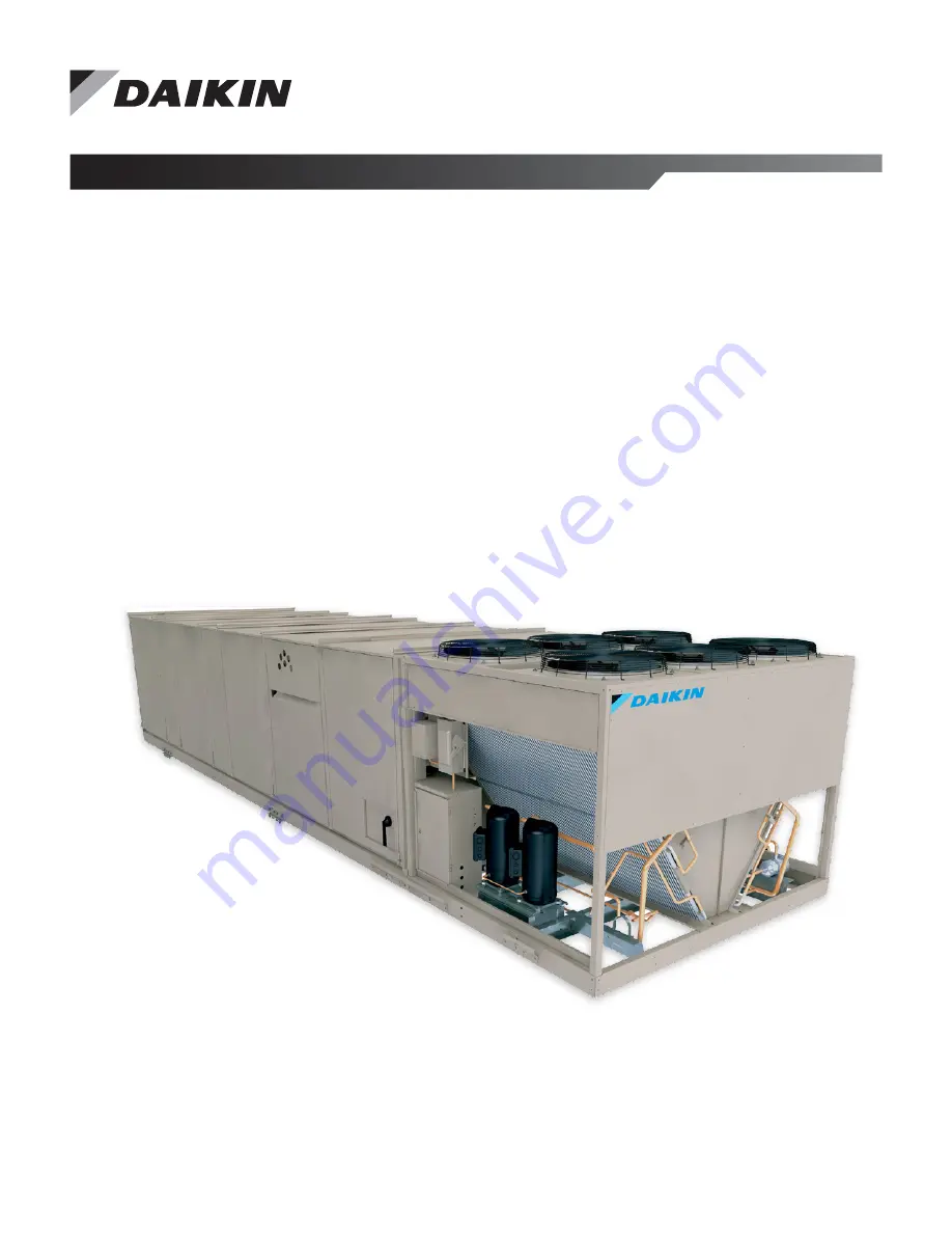
Page 4: ...nit with the locations of the major components Figure 4 shows a typical RDT unit with the locations of the major components These figures are for general information only See the project s certified s...
Page 5: ...Introduction www DaikinApplied com 5 IM 893 10 ROOFPAK SINGLEZONE UNITS Figure 4 Component Locations RDT Units 1 5 NPT drain...
Page 6: ...D L K N M H F I E P P O A Compressor 1 2 or 3 per circuit B Discharge line C Condenser coil D Evaporator coil E Manual charging evacuation valve F Filter drier H Sightglass I Liquid line J Suction li...
Page 7: ...Discharge plenum section Condensor section RAT LT11 optional S11 REC11 OAE ACT3 PC5 S10 REC10 LT10 HL22 EFT SD1 VM1 DAT ACT5 optional HTR1 2 HTR3 4 optional optional optional optional optional optiona...
Page 8: ...ending on the particular unit options following figures These figures show a typical unit See Wiring Diagrams on page 51 for the legend and configuration Specific unit configurations may differ slight...
Page 9: ...Introduction www DaikinApplied com 9 IM 893 10 ROOFPAK SINGLEZONE UNITS Figure 10 Typical Main Control Panel 045D to 075D 460 Volt...
Page 10: ...IM 893 10 ROOFPAK SINGLEZONE UNITS 10 www DaikinApplied com Introduction Figure 11 Typical Main Control Panel 080D to 140D 460 Volt...
Page 11: ...ROOFPAK SINGLEZONE UNITS Figure 12 Typical Gas Heat Panel 1000 MBh High TD Figure 13 Typical Prop Exhaust Panel 3 Fans 460 Volt Figure 14 VFD Bypass Panel 40 HP 460 Volt S3 FSG FSG Time LS1 LS2 AS IT...
Page 12: ...IM 893 10 ROOFPAK SINGLEZONE UNITS 12 www DaikinApplied com Introduction Figure 15 RCS Control Panel with MicroTech III RPS 045D to 079D Figure 16 RCS Control Panel with MicroTech III RPS 080D to 140D...
Page 13: ...9D Figure 18 VFD Compressor Panel SIzes 016D 074D Figure 19 Electric Heat Panel Sizes 080D to 140D GLG3 DS3 M41 M43 FB41 FB42 FB43 H53 TB11 M31 M32 M33 FB31 FB32 FB33 M42 Fan M4 Fan M3 LCP Local Contr...
Page 14: ...nApplied com Introduction Figure 20 Harness Plug Connector Detail LT OP1 LT OP2 LT11 LT10 COMP6 COMP5 COMP3 COMP4 COMP1 COMP2 DFRH DFLH OPEN4 SD1 SD2 GSHT1 GSHT2 HL22 OPEN3 OAE PC7 PC5 ACT3 OPEN2 SV12...
Page 15: ...han return air enthalpy use RAE Auto Economizer section Fully CW past D when used with RAE A D N A N A 049262201 OAT Outside air temperature sensor Senses outside air temperature N A N A N A N A N A 0...
Page 16: ...does not apply to units with VFD compressors Table 3 R 410A FanTrol Setpoints in F with MicroTech III Controls Unit Size Degrees Farenheit D07a D08b PC13 PC23c Setpoint Differential Setpoint Different...
Page 17: ...trols 1 Fan PC13 PC23 90 125 35 PC13 PC23 Controls 1 Fan 081 TC12 70 75 5 TC12 Controls 1 Fan PC13 PC23 90 12 35 PC13 PC23 Controls 1 Fan 085 TC12 65 70 5 TC12 Controls 1 Fan PC13 PC23 90 125 35 PC13...
Page 18: ...onventions and locations for each unit size Table 5 Condenser Fan Arrangement Unit size Refrigerant circuit Arrangement Unit size Refrigerant circuit Arrangement 015 016 025 026 020 021 1 2 074 1 2 03...
Page 19: ...lly trained personnel Receiving Inspection When the equipment is received all items should be carefully checked against the bill of lading to be sure all crates and cartons have been received If the u...
Page 20: ...nd screens around the unit maintaining the clearances specified see Figure 21 This is particularly important to prevent blowing snow from entering outside air intake and to maintain adequate head pres...
Page 21: ...mold growth when damp Such materials must be protected from moisture that can enter units during maintenance or normal operation These flanges must not support the total weight of the ductwork See Ins...
Page 22: ...tight 4 Square entire curbing assembly and securely tighten all bolts 5 Position curb assembly over roof openings Curb must be level from side to side and over its length Check that top surface of th...
Page 23: ...56 2 1427 030D 20 508 035 040 57 3 1455 035D 040D 20 508 045 050 062 068 61 0 1594 045D 075D 28 0 711 010 021 026 031 042 051 061 070 080 085 090 100 105 74 0 1880 080D 090D 38 0 965 081 091 101 110 1...
Page 24: ...00 2438 to 2540 mm wide to prevent damage to the unit cabinet Avoid twisting or uneven lifting of the unit The cable length from the bracket to the hook should always be longer than the distance betwe...
Page 25: ...50 062 068 36 5 051 063 070 071 075 079 080 085 090 100 105 30 0 081 091 101 110 140 38 0 For all units or shipping sections without condensers Y 0 Installation Z total base rail length of the units N...
Page 26: ...e nameplate is attached to the air handler section and power is fed to both sections through the main control box as in a non split RPS RDT unit Field reassembly of an RPS RDT unit that has shipped sp...
Page 27: ...of splice cap 3 Caulk watertight vertical seam 4 Install 10 screws provided 5 Install screws 0 25 20 0 75 removed in Phase I Step 2 6 Install splice cover provided Figure 32 Reassemble Cabinet Reinst...
Page 28: ...ernal raceway covers on either side of the unit split 4 Remove the excess harness length from the external raceway on the DX side of the split then route along the raceway through the bushed hole in t...
Page 29: ...eet of horizontal run in the direction of refrigerant flow to assist oil return Pressure drops in the refrigerant lines should be maintained at or below the ASHRAE recommendations and line lengths sho...
Page 30: ...1 2 6 62 6 62 6 62 6 62 6 62 6 62 Table 10 015D 140D Piping Diameter Component Circuit Piping Diameter inches 015D 016D 020D 021D 025D 026D 030D 031D 035D 042D 045D 050D 051D 061D 063D 068D Liquid li...
Page 31: ...then be leak tested with halide or electronic leak detector After making any necessary repair the system should be evacuated as described Evacuation After determining the unit is tight and there are...
Page 32: ...9 120D 35 37 39 41 5 3 6 7 2 9 125D 38 3 42 41 6 7 2 9 130D 38 37 42 41 6 7 2 9 140D 38 40 42 44 6 7 2 9 DX coil configuration S Standard L Large is identified by the 8th digit of the RPS RDT or RFS m...
Page 33: ...ted it can be charged as described in the paragraphs following Connect the refrigerant drum to the gauge port on the liquid charging valve and purge the charging line between the refrigerant cylinder...
Page 34: ...leaving the condenser and the temperature corresponding to the compressor saturated discharge pressure It is important not to use the saturation pressure at the condenser outlet as this will lead to...
Page 35: ...drain pan through a copper tube near the center of the drain pan Check that this tube is open before putting the unit into operation and as a part of routine maintenance Drain pans in any air conditi...
Page 36: ...e serious damage 2 Do not reduce pipe size at the coil return connection Carry return connection size through the dirt pocket making the reduction at the branch leading to the trap 3 Install vacuum br...
Page 37: ...inkage adjustment of the factory installed option Economizer Dampers Outside air intake is provided on both sides of the unit and the return air path is at the center of the damper set As the single a...
Page 38: ...dampers are intended to remain at a fixed position during unit operation providing fresh air quantities from 0 to 30 of the total system airflow depending on the damper setting This setting is made a...
Page 39: ...lled in units with side discharge access to plenum mounted components is difficult On bottom supply bottom return units if a Daikin roof curb is not used installing contractor should make an airtight...
Page 40: ...ure 4 Locate the duct tap in a non turbulent flow area of the duct Keep it several duct diameters away from take off points bends neckdowns attenuators vanes or other irregularities 5 Use a static pre...
Page 41: ...he inch HI fitting for sensor SPS2 5 Locate the reference pressure LO tap on the roof Keep it away from the condenser fans walls or anything else that may cause air turbulence Mount it high enough abo...
Page 42: ...are provided with internal power wiring for single or dual point power connection The power block or an optional disconnect switch is located within the main control panel Field power leads are brough...
Page 43: ...nit to powerblock PB4 or an optional disconnect switch DS4 located in the condenser control panel of the RCS unit Power leads enter the bottom left corner of the condenser control panel through the co...
Page 44: ...e with the National Electrical Code an electrically isolated 115V circuit is provided in the unit to supply the factory mounted service receptacle outlet and optional unit lights This circuit is power...
Page 45: ...le and lights are made at terminal block TB7 which is also located in the main control panel Refer to Figure 51 Figure 52 and Control Panel on page 8 Two 7 8 knockouts are provided for wire entry RFS...
Page 46: ...pression perform the following 1 Loosen the 0 625 18 UNF hex nut Figure 55 2 Place additional weight on the fan sled frame and use a lever to slightly compress the spring or raise the sled This will a...
Page 47: ...ng in a normal manner there should be no contact between the snubber restrainer angle and the snubber neoprene bumper However in a seismic event the snubber will limit movement of the spring mounted f...
Page 48: ...double width fans are mounted on springs After the spring mounts are adjusted for level operation when the fan is running check the thrust restraints With the fan off set the adjustment nuts so the sp...
Page 49: ...nd SD2 line 237 The time clock S7 switch and emergency shutdown terminals lines 217 222 control fan operation NOTE Unit ships with factory installed jumpers between TB2 101 and 105 and between 101 and...
Page 50: ...heaters HTR 1 2 3 and 4 lines 836 848 853 and motor protectors MP1 2 3 and 4 lines 836 848 854 This same 115 V ac source also goes through System switch S1 line 203 Figure 68 on page 64 The optional p...
Page 51: ...Fuseblock electric heat bottom bank Electric heat box FB65 Fuseblock evap cond sump heater Main Cond control box ID Description Standard location FD Flame detector Heat section gas FLC Fan limit cont...
Page 52: ...8 Relay return fan enable Main control box R69 Relay Inv bypass VAV box interlock Main control box R70 79 Relay use on specials Main control box RAE Return air enthalpy sensor Return section RAT Retur...
Page 53: ...om 53 IM 893 10 ROOFPAK SINGLEZONE UNITS General Notes 1 Field wiring 2 Factory wiring 3 Shielded wire cable 4 Main control box terminals 5 Auxilliary box terminals 6 Field terminals 7 Plug connector...
Page 54: ...IM 893 10 ROOFPAK SINGLEZONE UNITS 54 www DaikinApplied com Wiring Diagrams Figure 60 VAV Fan Power With SAF and RAF VFDs and Unit Powered Outlet Light Circuit...
Page 55: ...Wiring Diagrams www DaikinApplied com 55 IM 893 10 ROOFPAK SINGLEZONE UNITS Figure 60 continued VAV Fan Power With SAF and RAF VFDs and Unit Powered Outlet Light Circuit...
Page 56: ...T 1 CUSTOMER SUPPLIED POWER 106 107 108 109 110 111 112 113 133 134 135 136 137 138 139 140 141 426 109 426 MTR T3 T2 T1 T3B T3A T2B T2A T1B T1A L3B L3A L2B L2A L1B L1A T3 T2 L3 L2 1 L 1 T G T3 T2 T1...
Page 57: ...47 148 149 150 151 152 161 162 163 164 165 166 167 168 169 170 109 431 109 426 MTR 2 1 2 1 2 1 X3 X1 X2 H4 H3 H2 H1 1 2 3 4 5 6 7 8 GRD L3 1 L2 1 L1 1 T3 T2 T1 T3 T2 L3 L2 T1 L1 T3B T3A T2B T2A T1B T1...
Page 58: ...0 ROOFPAK SINGLEZONE UNITS 58 www DaikinApplied com Wiring Diagrams Figure 62 RPS 074 Condensing Unit Power with Variable Speed Inverter Compressor V L2 W L3 U L1 Related control schematic on page 69...
Page 59: ...Wiring Diagrams www DaikinApplied com 59 IM 893 10 ROOFPAK SINGLEZONE UNITS Figure 63 RPS 075 Condensing Unit Power With SpeedTrol and Fixed Scroll Compressors...
Page 60: ...IM 893 10 ROOFPAK SINGLEZONE UNITS 60 www DaikinApplied com Wiring Diagrams Figure 64 VFD Control SAF and RAF...
Page 61: ...Wiring Diagrams www DaikinApplied com 61 IM 893 10 ROOFPAK SINGLEZONE UNITS Figure 65 VAV Control Inputs...
Page 62: ...IM 893 10 ROOFPAK SINGLEZONE UNITS 62 www DaikinApplied com Wiring Diagrams Figure 65 continued VAV Control Inputs...
Page 63: ...D PL18 3 M X4 R2 4 5 9 PL18 4 PL18 5 VM1 T2 T1 T3 _N R2 0 13 14 DO1 203E C1 DO 1 T2_115 VAC 268 T1_N 168 EXP B 168A PL18_8 HL23 PL19 9 1 2 1 2 LS1 LS2 PL 19 6 PL 19 7 PL19 8 CO M NO CO M NO DO2 EXP B...
Page 64: ...ive to its minimum low fire position At the completion of the FSG prepurge cycle the valve will be at the minimum open position and the minimum position switch LS1 will be made providing a digital inp...
Page 65: ...Wiring Diagrams www DaikinApplied com 65 IM 893 10 ROOFPAK SINGLEZONE UNITS Figure 67 Electric Heat Control...
Page 66: ...IM 893 10 ROOFPAK SINGLEZONE UNITS 66 www DaikinApplied com Wiring Diagrams Figure 67 continued Electric Heat Control...
Page 67: ...Wiring Diagrams www DaikinApplied com 67 IM 893 10 ROOFPAK SINGLEZONE UNITS Figure 68 RPS 061 Condensing Unit Control With Fixed Speed Scroll Compressors...
Page 68: ...IM 893 10 ROOFPAK SINGLEZONE UNITS 68 www DaikinApplied com Wiring Diagrams Figure 68 continued RPS 061 Condensing Unit Control With Fixed Speed Scroll Compressors...
Page 69: ...Wiring Diagrams www DaikinApplied com 69 IM 893 10 ROOFPAK SINGLEZONE UNITS Figure 69 RPS 074 Condensing Unit Control with Vaiable Speed Inverter Compressors...
Page 70: ...893 10 ROOFPAK SINGLEZONE UNITS 70 www DaikinApplied com Wiring Diagrams Figure 69 continued RPS 074 Condensing Unit Control with Vaiable Speed Inverter Compressors Related control schematic on page...
Page 71: ...Wiring Diagrams www DaikinApplied com 71 IM 893 10 ROOFPAK SINGLEZONE UNITS Figure 70 RPS 074 Compressor Control with Variable Speed Inverter Compressor...
Page 72: ...O2 RETURN FAN 207 jprs 24V SRC MCB 1 1NO BO1 SUPPLY FAN 207 6 1 9 C R S MCB 207 11 31 MMP10 12 32 11 31 MMP20 12 32 TO MOTHERBOARD WIRED INTERNAL SOURCE 9 16 T3_COM 1 1 3 T3_24V 1 1 3 115VAC_GF 1 T1_N...
Page 73: ...rol OAE Units with MicroTech III control and an economizer come standard with an electromechanical enthalpy control device OAE that senses both the humidity and temperature of the outside air entering...
Page 74: ...round fault relay employs solid state circuits that will instantly trip and open a set of relay contacts in the 115 volt control circuit to shut the unit down whenever a ground fault condition exists...
Page 75: ...to lower the moisture content of the air and then reheated to comfort conditions Figure 74 Dual 2 Way Valve Refrigeration Schematic Figure 75 Ideal for Neutral Air Ventilation Control For variable spe...
Page 76: ...air of interface boards which in turn supply the control signal to the reheat valves step type In the Fan Only state no sensible cooling is required but the dehumidification mode will still be enabled...
Page 77: ...s NOTE The regulating valve opening point can be determined by slowly reducing the system load or reducing the required discharge air temperature setting while observing the suction pressure When the...
Page 78: ...in wired to TB2 and the supply air smoke detector can be wired between terminals 103 and 104 and the return air smoke detector can be wired between terminals 104 and 105 The T2 transformer supplies 2...
Page 79: ...tat detects a freezing condition while the fan is off the MicroTech III controller opens the heating valve and sets a 10 minute timer The MicroTech III controller s active alarm is Freeze Problem When...
Page 80: ...To use this signal wire the coil of a field supplied and installed 24 V ac pilot relay across terminals 116 and 117 on TB2 When this output is ON 24 V ac is supplied from the T3 control transformer t...
Page 81: ...open when the discharge plenum pressure rises to 3 5 wc 872 Pa This setting should be correct for most applications however it is adjustable Removing the front cover of the device reveals a scale sho...
Page 82: ...ccordingly The pressure transducer is calibrated to provide a 1 0 to 5 0 V dc signal with a 8 to 30 V dc input starting at 1 0 V dc 250 psig and up to 5 0 V dc 400 psig In order to maintain an accepta...
Page 83: ...Level in which the VFD will stop the condenser fan motors under certain conditions If the head pressure were to fall below 250 PSIG with the condenser fans operating at minimum speed of 10Hz possibly...
Page 84: ...uvered outdoor air intake door on the side of the unit see Figure 84 3 The swinging vane on the measurement station is locked in place for shipment Unlock it by removing the two shipping screws One is...
Page 85: ...f the fulcrum b Its top thumbscrew rests against the vertical alignment mark on the vane NOTE The alignment mark is located 0 50 inch in from the bend on the outer edge of the vane It intersects with...
Page 86: ...rning the long adjuster nut to decrease the L dimension in Figure 89 NOTE If the necessary adjustment cannot be made using the long adjuster nut reposition the two 1 4 20 NC jam nuts on the threaded r...
Page 87: ...ed from the motor Always check motor load amperage and compare to name plate rating when changing fan speed Figure 91 Fan Rotation Once the fan is put into operation set up a periodic maintenance prog...
Page 88: ...tment should be performed in small increments since the blades will not fully close if the brackets are bent to far NOTE Performing adjustment 2 will have a small effect on adjustment 1 Therefore if a...
Page 89: ...ropeller Excessive Noise Bearings Tighten bearing collars and setscrews Lubricate bearings Replace defective bearings V Belt drive Tighten pulleys on motor shaft and fan shaft Adjust belt tension Alig...
Page 90: ...or fan panel and entire propeller periodically Dirt can clog cooling openings on motor housings contaminate bearing lubricant and collect on propeller blades causing severe imbalance if left unchecked...
Page 91: ...h S1 is closed and all doors with door power disconnect switches are closed To turn the lights off disconnect power to the entire unit or open system switch S1 The normally open disconnect switches ar...
Page 92: ...al rooms located on each floor Each remote user interface offers the same functionality as its unit mounted counterpart including Push and roll navigation wheel with an 8 line by 30 character display...
Page 93: ...Unit Options www DaikinApplied com 93 IM 893 10 ROOFPAK SINGLEZONE UNITS Figure 100 Specifications and Connections...
Page 94: ...e available fixed compressor with the fewest run hour total is started while the VFD compressor is reduced to minimum speed at which point it resumes modulating to maintain the discharge temperature W...
Page 95: ...ing speed before staging up a fixed compressor The VFD is held at minimum speed for 30 seconds before normal modulation resumes Compressor Stage Down Transition When the VFD compressor has been operat...
Page 96: ...ditional 15 minutes If low oil indication still does not clear within these 15 minutes the VFD compressor will be locked out on alarm The low oil problem is also generated and the VFD compressor circu...
Page 97: ...speed for 10 minutes and if superheat remains below 20F the VFD compressor speed is increased an additional 5 rps When compressor discharge superheat level is at 20F or above the compressor speed is...
Page 98: ...xceeds 250 PSIG When the VFD compressor reaches 250 PSIG this speed becomes the new minimum speed of the VFD compressor As the discharge pressure rises above 250 PSIG the minimum allowable compressor...
Page 99: ...y control Variable speed compressor enhances energy efficiency and capable of providing unit capacity modulation down to15 and reduces compressor cycling and wear on compressor Daikin rooftop units wi...
Page 100: ...Dismanteling Optical Oil Level Sensor An optical oil sensor is used to monitor oil level in VFD compressor sump The sensor is mounted directly to a fitting on the VFD compressor shell and can be remov...
Page 101: ...oop configuration with 0 10Vdc reference corresponding to 1500 6000 Rpm The compressor drive drive generates a soft start with an initial ramp of 2 seconds In rush current or LRA to the VFD compressor...
Page 102: ...operly terminated 4 Verify that all electrical connections in the unit control panel and compressor terminal box are tight and that the proper voltage is connected 5 Verify all nameplate electrical da...
Page 103: ...3 14 linear stroke to open it fully Do not allow dampers to be driven beyond their normal full closed or full open position 1 Check whether the outdoor air is suitable for free cooling by displaying t...
Page 104: ...s when the compressor is energized If the compressor is rotating in reverse the sound level is louder and current draw is reduced substantially After several minutes of operation the compressor s moto...
Page 105: ...n Menu Quick Menu Ctrl Mode fan only 12 Check refrigerant circuit 2 by repeating steps 2 through 9 substituting circuit 2 nomenclature for circuit 1 nomenclature CS2 TD2 CCB2 and compressor 2 and 4 13...
Page 106: ...the valve to the coil The three way hot water valve is open to the coil when the valve stem is down If the unit loses power the spring in the actuator should drive the valve wide open to the coil Che...
Page 107: ...n at which the belt will not slip under peak load conditions 2 Check tension frequently during the first 24 48 hours of operation 3 Over tensioning shortens belt and bearing life 4 Keep belts free fro...
Page 108: ...This key projects a small amount to provide a grip for removing 3 Adjust the sheave pitch diameter for the desired fan speed by opening the moving parts by half or full turns from closed position Do...
Page 109: ...rely Adjusting 1 Slack off all belt tension by moving the motor toward the driven shaft until the belts are free from the grooves For easiest adjustment remove the belts 2 Loosen setscrews D 3 Loosen...
Page 110: ...s line up Reinsert locking screws A but do not tighten them until after adjustment is made 3 Adjust the sheave to the desired pitch diameter by turning the outer locking ring with a spanner wrench Any...
Page 111: ...ax RF SF Max Sup Fan Min RF SF Min 11 Set the economizer control parameters as required in keypad menu Main Menu View Set Unit Economizer OAD Econo Pos 12 Set the control timers as required in keypad...
Page 112: ...n the line contains a changeable value and the cursor is at that line the entire line is highlighted Each line on a page may also be defined as a jump line meaning pushing the navigation wheel will ca...
Page 113: ...from 3 to 30 minutes via the Timer Settings menu in the Extended Menus Figure 116 Password Main Page Figure 117 Password Entry Page Navigation Mode In the Navigation Mode when a line on a page contai...
Page 114: ...Spt 0 05in Reheat Cap XXX IAQ PPM XXXXppm Control Temp XXX OA Flw XXXXXCFM Occ Clg Spt 72 0 F MinOAFlw Spt 2000CFM Occ Htg Spt 68 0 F OA Temp XXX F Disch Air XXX F EW Temp XXX F Rel Humidity XXX About...
Page 115: ...6 Off Comp 3 Off Reheat Valve 0 Comp 4 Off RH Output Off Comp 5 Off LSCRH Valve Off Comp 6 Off HGBP Valve Off Comp 7 Off ERec Wheel Off Comp 8 Off ER Whl Cmd 0 U1 Comp 1 Off ERBP Dmpr Cl Off U1 Comp...
Page 116: ...mp XXX F EW Temp XXX F Mixed Air XXX F ER LAT XXX F ER EAT XXX F Sump Temp XXX F PA Temp XXX F DRT1 XXX F DRT2 XXX F DRT3 XXX F SRT XXX F DFT XXX F IRT XXX F ORT XXX F INVCompTemp XXX F Occupancy Occu...
Page 117: ...MMDD YY HH MM OPTIMAL START Enable No Htg Range 0 4 F min Htg OAT 35 F Des Htg OAT 0 F Clg Rate 0 4 F min Clg OAT 85 F Des Clg OAT 95 F DAYLIGHT SAVINGS DLS Strt Mon Mar DLS Strt Wk 2nd Week DLS End M...
Page 118: ...600 Duct Press 1 X Xin V A Min CFM 0V ECM Status __________ Duct Press 2 X Xin V A Max CFM 10 V 1 ZONE VAV CONTROL SAF CFM DB 3 Min Clg Spd 40 SAF CFM Period 30s Max Clg Spd 100 SAF CFM Gain 0 1 Min H...
Page 119: ...2s ExhMxOAPos 100 Max Spd Chg 4 Exh Stg 1 On 40 Sup Fan Max 100 Exh Stg 1 Off 30 RF SF Max 95 Exh Stg 2 On 55 Sup Fan Min 30 Exh Stg 2 Off 40 RF SF Min 25 Exh Stg 3 On 70 Lo Fan Diff 75 Exh Stg 3 Off...
Page 120: ...A 65s R22 Air Flw Ing 120s Sens Alm Dly 30s Temp AlmDly 30s ALARM CONFIG Emerg Stop ManClr Exp Valve Set Up EXP VALVE STATUS EXP VALVE SETUP EVI Pos XXX SSH DB 2 0 F EVO Pos XXX SH Lo Base 6 0 F 5 0 F...
Page 121: ...R EAT XXX F Min ExhT Diff 2 0 F Max ExhT Diff 6 0 F ER Whl Stg Tm 5min ER Whl Off Tm 20min Rel Humidity XXX Min Whl Spd 5 Intersect Pt XXX X F Fst Mgnt Meth Timed OA Frst Temp 20 56 F Defrost Time 5mi...
Page 122: ...o Alarm 1 Alarm Type Alarm 2 Alarm Type Alarm 10 Alarm Type Save Restore Set tings Save Params No Rstr Params No Rstr Factory No SaveToCard No LoadFromCard No CreateTrace No Trace To SD No Service Men...
Page 123: ...Input Status MCB DI1 ____________ MCB DI2 ____________ MCB DI3 ____________ MCB DI4 ____________ MCB DI5 ____________ MCB DI6 ____________ EMD DLA1 __________ Digital Output Status MCB DO1 __________...
Page 124: ...ch Air 0 0 F Return Air 0 0 F Space Temp 0 0 F OA Temp 0 0 F EF LC Temp 0 0 F EW Temp 0 0 F Mixed Air 0 0 F MAT LON SCC 0 0 F ER LAT 0 0 F ER EAT 0 0 F Sump Temp 0 0 F DRT1 0 0 F DRT3 0 0 F SRT 0 0 F...
Page 125: ...MM SS IFB Comm Status IFB SW Vers VP0329008 IFBCommStatus ____ PrvCommStatus _______ MM DD YYYY HH MM SS ACS1 DataRcvd _______ ACS3 DataRcvd _______ Fault Code Details ACTIVE FAULT CODES INVAlarmCode...
Page 126: ...tance Name Min OA Reset None Apply Changes No HEAT COOLCHANGEOVER Ctrl Temp SRC RAT AplyTstatChg No Use Tstat Spt No Occ Clg Spt 72 F Occ Htg Spt 68 F FAN CONTROL OPTIONS SAF Ctlr DSP RF EF Ctlr Track...
Page 127: ...ce technician The required frequency of inspections depends upon the total operating time and the indoor and outdoor environmental conditions Routine maintenance should cover the following items Tight...
Page 128: ...ay collect on components inside the units To prevent surface rust and discoloration spray all bare metal parts with a rust preventive compound Pay close attention to fan shafts sheaves bearings and be...
Page 129: ...d amoun hown in Table 22 Start bearing and run for a few minutes Stop bearing and add the second half of the recommended amount A temperature rise sometimes 30 F 1 C after relubrication is normal Bear...
Page 130: ...llation area and keep well lit Be sure mounting surfaces are clean and flat 2 2 Check shaft Shaft should be within tolerance range shown in Table 27 clean and free of nicks and burrs Mount bearing on...
Page 131: ...hs Setscrews Setscrews are used to lock sheaves locking collars and fan wheels to their shafts They must be checked periodically to see that they have not loosened If this is not done severe equipment...
Page 132: ...rings 2 Loosen the fan hub setscrews and move the wheel s along the shaft as necessary to obtain the correct dimension shown in Table 31 Table 32 and Table 33 3 Retighten the setscrews to the torque s...
Page 133: ...es A 0 3 0 0 27 9 9 246 mm 30 10 6 269 mm 33 11 7 297 mm 36 13 1 333 mm 40 14 5 368 mm0 Figure 123 44 and 49 SWSI Airfoil Wheel to Funnel Table 32 44 and 49 SWSI Airfoil Wheel to Funnel Relationship W...
Page 134: ...trio assemblies three refrigerant lines must be disconnected and re assembled 1 TPTL Oil Equalization Line a This line Figure 125 contains the oil sight glass b This line connects to each compressor...
Page 135: ...place 9 Braze the tubes into place Figure 129 Micro Channel Coil Cross Section All Aluminum Condenser Coils The condenser coils are an all aluminum design including the connections micro channels fin...
Page 136: ...e following cleaning procedures are recommended as part of the routine maintenance activities for Option E Coated Coils Documented routine cleaning of Option E Coated Coils is required to maintain war...
Page 137: ...Remover Chlor Rid Int l Inc P O Box 908 Chandler AZ 85244 800 422 3217 Chlor Rid DTS CHLOR RID DTS should be used to remove soluble salts from the Option E Coated Coil but the directions must be foll...
Page 138: ...res are stop valves that do not allow refrigerant to flow through the Shrader unless the device is in place Therefore the low pressure and SpeedTrol sensors switches can be replaced without reclaiming...
Page 139: ...a new device with incorrect setpoint adjustment Any other non authorized trip point or setpoint adjustment voids all or portions of the unit s warranty Authorized setpoint adjustments accomplished as...
Page 140: ...tems options Screw type spring loaded and ring cable lug connection Switch position indicator to indicate a trip and TEST function for wiring Large rotary button to adjust current to Motor RLA Selecto...
Page 141: ...is deactivated after a specified trip delay Trip Delay The output relay reactivates after power line conditions return to an acceptable level for a specified amount of time Restart Delay The trip and...
Page 142: ...nnect is a molded case switch with similar features of the circuit breaker The through the door feature provides a safety interlock that disables power when the control panel door is opened Opening th...
Page 143: ...cedure Also check for faulty wiring connections at the VFD analog inputs The controller displays and controls to the lower of the two readings If a sensor is defective and inputs 0 volts to the VFD th...
Page 144: ...SCC units only 111048102 DAT Discharge Air Temperature Sensor 50 ft cable length field cut to length 060004705 EFT Entering Fan Air Temperature Sensor 50 ft cable length field cut to length 060004705...
Page 145: ...nly the failed portion of the trio may need replacement Replacing a Portion of a Tandem or Trio The decision to replace the failed portion of the tandem or trio as opposed to replacing the entire tand...
Page 146: ...the compressor If the compressor is not returned you will be billed for the replacement compressor 5 Consideration may be given at this time to a compressor teardown analysis depending on the history...
Page 147: ...ination and this warranty shall expire twelve 12 months from that date Exceptions 1 If free warranty labor is available as set forth above such free labor does not include diagnostic visits inspection...
Page 148: ...__________ Serial number ___________________________________ Compressor 5 model number ________________________________________ Serial number ___________________________________ Compressor 6 model num...
Page 149: ...id line shutoff valve Circuit 1 _________ psig Circuit 2 _________ psig Liquid temperature fully loaded 2 3 compressors Circuit 1 _________ psig Circuit 2 _________ psig G Suction line temperature Cir...
Page 150: ...off OK Yes No N A VIII Design Flow Calibration A Verify power is supplied to the MicroTech III unit controller Yes No N A B Verify that the shipping screws have been removed from the measuring station...
Page 151: ...ions of the unit fit together properly Yes No N A 4 Did the cabinet have any air leakage Yes No N A Location on unit ___________________________________________________________________________ 5 Were...
Page 152: ...nt to its standard terms and conditions of sale including Limited Product Warranty Consult your local Daikin Applied representative for warranty details To find your local Daikin Applied representativ...