REMOVAL
PROCEDURE
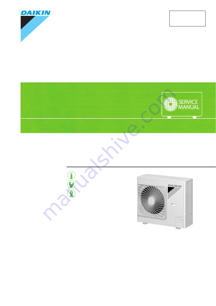
S E R V I C E M A N U A L
Outdoor Unit
Non-Inverter
Pair Type
6.0 kW Class
Si01-881
Page 1: ...REMOVAL PROCEDURE S E R V I C E M A N U A L Outdoor Unit Non Inverter Pair Type 6 0 kW Class Si01 881 ...
Page 2: ...Service Manual Removal Procedure Outdoor Unit zCooling Only R60GV1G ...
Page 3: ...881 Removal Procedure 1 Table of Contents 1 Removal of Outer Panels 2 2 Removal of Fan Motor Outdoor Fan 5 3 Removal of Electrical Components ASSY 7 4 Removal of Sound Blankets 11 5 Removal of Compressor 12 ...
Page 4: ...ning off all power supplies before disassembling work Step Procedure Points 1 Remove the top panel 1 Remove the 8 screws of the top panel 2 Pull the suction grille to unfasten the hook Take care not to cut your finger by the fins of the outdoor heat exchanger 3 Lift up and remove the top panel Top panel R5423 R5424 R5425 Suction grille R5426 ...
Page 5: ... the suction grille 2 Remove the front panel 2 1 Remove the screw and remove the front panel 2 When reassembling fit the 5 hooks 3 Remove the piping cover front 1 Remove the screw and remove the piping cover front Step Procedure Points Hook R5427 R12807 Front panel 2 R12808 Hook Hook Piping cover front R13234 ...
Page 6: ...Removal of Outer Panels Si01 881 4 Removal Procedure 4 Remove the front panel 1 1 Remove the 6 screws and remove the front panel 1 Step Procedure Points Front panel 1 R12810 R5432 R8322 ...
Page 7: ... panel according to the Removal of the Outer Panels 1 Disconnect the relay connector for the fan motor 2 Disconnect the 2 terminals for the fan motor capacitor C1 3 Unfasten the hook with a flat screwdriver Put the fan motor lead wire through the back of the fan motor when reassembling so as not to be entangled with the outdoor fan 4 Release the fan motor lead wire from the partition plate R8330 R...
Page 8: ... the nut and remove the outdoor fan 3 Remove the fan motor Be sure to remove the lower screws first If the upper screws are removed first the fan motor may tilt or fall because the center of its gravity is toward the front It may cause injuries 1 Remove the 4 screws and remove the fan motor Step Procedure Points Lock washer R5438 13 mm R12301 R12834 D cut D cut Lock washer R12835 R5439 ...
Page 9: ...wait 10 minutes or more after turning off all power supplies before disassembling work Step Procedure Points 1 Remove the side panel Preparation Remove the top panel front panel 1 2 and piping cover front according to the Removal of Outer Panels 1 Remove the 9 screws and remove the side panel Side panel R5440 R8333 Side panel R5442 Hook ...
Page 10: ...emove the sensor fixing plate 1 Detach the outdoor temperature sensor 2 Disconnect the terminals of the outdoor temperature thermostat S1T 3 Remove the screw and remove the outdoor temperature thermostat Step Procedure Points R12813 Outdoor temperature sensor R12814 R12815 Outdoor temperature thermostat S1T R8335 ...
Page 11: ...e the capacitor 1 Disconnect the terminals from the capacitor C2 4 Disconnect the each wire harness 1 Cut the clamp 2 Disconnect the blue terminal K1M 2 3 Detach the clamp for the compressor lead wire rear side Step Procedure Points Capacitor C2 R12816 R8337 R8338 Blue R6749 ...
Page 12: ...al Components ASSY Si01 881 10 Removal Procedure 5 Remove the electrical components ASSY 1 Lift the electrical components ASSY to unfasten the 2 hooks and remove it Step Procedure Points R12817 Electrical components ASSY ...
Page 13: ...l power supplies before disassembling work Step Procedure Points 1 Remove the sound blanket top Preparation Remove the electrical box according to the Removal of Electrical Components ASSY Since the piping ports on the sound blanket are torn easily remove the blanket carefully 2 Remove the sound blanket body R12818 Sound blanket top Sound blanket body R5454 ...
Page 14: ...ll power supplies before disassembling work Step Procedure Points 1 Remove the terminal cover 2 Disconnect the compressor lead wires Be careful so as not to burn the compressor terminals or the name plate S Yellow C Blue R Red 3 Remove the gasket R5455 Terminal cover Terminal cover fixture R5456 R5457 Yellow S Blue C Red R R12819 S R C Gasket R5458 ...
Page 15: ...Keep below 120 C For the sake of this wrap the four way valve with wet cloth and provide water so that the cloth does not dry In case of difficulty with gas brazing machine 1 Disconnect the brazed part where is easy to disconnect and restore 2 Cut pipes on the main unit with a tube cutter in order to make it easy to disconnect Before working make sure that the refrigerant is empty in the circuit B...
Page 16: ...Revision History Month Year Version Revised contents 06 2013 Si01 881 First edition ...
Page 17: ...sories supplied or specified by Daikin Ask a qualified installer or contractor to install those parts and accessories Use of unauthorised parts and accessories or improper installation of parts and accessories can result in water or refrigerant leakage electrical shock fire or explosion z Read the User s Manual carefully before using this product The User s Manual provides important safety instruc...