IM 1285-4 • MICROTECH III 20 www.DaikinApplied.com
Appendix
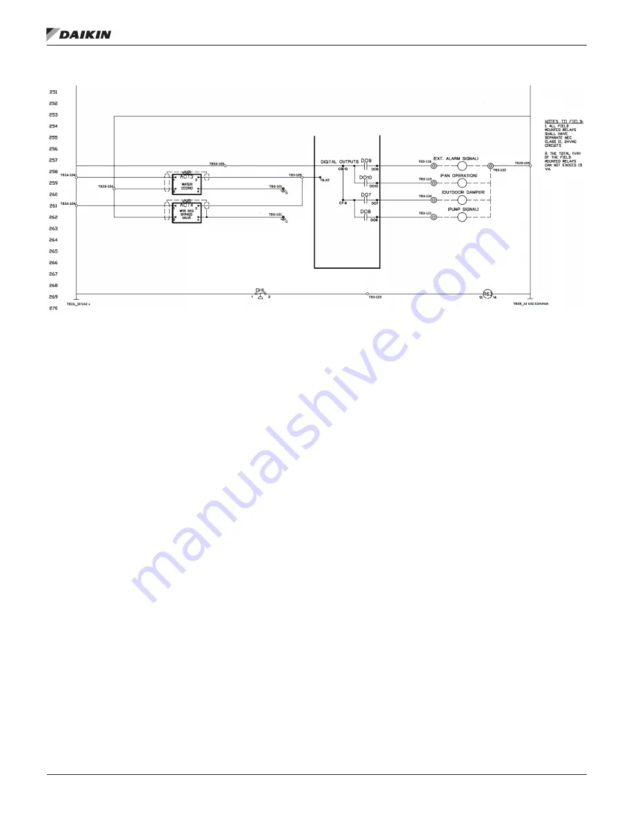
Figure 26 continued: 200s Wiring Diagram
Page 1: ...Installation and Maintenance IM 1285 4 Group Applied Air Systems Part Number IM 1285 Date January 2022 Self Contained Systems MicroTech I to MicroTech III Unit Controller Conversion ...
Page 2: ...low Sensor 10 Installing the VFD 10 Wiring 11 Wiring to the MicroTech III 11 Wiring the Terminal Blocks and Transformers 11 Wiring Power to the MicroTech III MCB 11 Wiring Temperature Sensors 12 Wiring Pressure Switches PC5 PC7 and DHL and R63 Relay 13 Wiring High Pressure Switches 1 2 and HP1 HP2 Relays 14 Wiring High Pressure Switches 3 4 and HP3 HP4 Relays 14 Wiring Low Pressure Switches 1 2 Fr...
Page 3: ...P A B and C 193407501 3 HMI Display 350147416 1 Controller Terminal Block 2 pole 193410302 4 Controller Terminal Block 3 pole 193410303 8 Controller Terminal Block 5 pole 193410305 1 Controller Terminal Block 6 pole 193410306 1 Controller Terminal Block 7 pole 193410307 3 Controller Terminal Block 8 pole 193410308 6 Terminal 2 2 spring Grey 2 row Jumper Ports 349930641 75 Terminal 2 2 Spring Green...
Page 4: ...ucture improved metrics trending data capability and network compatibility Each Self Contained unit will have small differences such as the number of compressors or a VFD for the supply fan Recognizing these differences and following the instructions throughout the manual will ensure a successful conversion NOTICE Follow all Lock Out Tag Out procedures to minimize risks of injury during this proce...
Page 5: ...Introduction www DaikinApplied com 5 IM 1285 4 MICROTECH III Figure 3 Output Board Figure 4 Input Board ...
Page 6: ... 5 below shows the control panel with all wiring labeled and boards removed Figure 5 Control Panel without Components Removing Temperature Sensors Pressure Sensors and Pressure Switches The following temperature sensors will need to be removed from the unit DAT RAT MAT EWT Be aware and take note of the mounting location for each of these sensors because new sensors will be remounted and wired to t...
Page 7: ...III MCB onto the DIN rail and engage the tabs to secure it in place Depending on the application one or more Expansion Modules may be needed to be connected to the MT III MCB To install an Expansion Module slide the 8 pin connector into the left side of the Module and then slide the other end into the right side of the MT III MCB Multiple Expansion Modules can be mounted to the right of the prior ...
Page 8: ...allation as necessary See the wiring section of this manual for more information on where to wire additional relays for more than four compressors Terminal Blocks In order to ensure organization and accuracy when wiring five terminal blocks are required to be installed in the control panel of the unit Each terminal block needs to be mounted on a DIN rail and is assembled by sliding each of the sin...
Page 9: ...l is mounted on the entering face of the economizer coil Upon sensing a temperature above specification the unit shuts down opens the hydronic control valves and sends an alarm indication via the MicroTech III controller The freezestat has a field adjustable set point range of 35 F to 45 F To change the set point turn the adjustment screw until the pointer is opposite the desired cutout point The ...
Page 10: ...t designed for a Variable Air Volume Application will need a VFD installed for desired operation The VFD can be mounted using screws on the outer frame of the unit to the left or right of control panel Two holes need to be drilled below the VFD and into the control panel for power and signal wiring conduit See Figure 13 and Figure 14 NOTE Daikin only supports installing ABB ACS320 ACH550 and ACH58...
Page 11: ...ross the terminal blocks See diagram in Figure 15 Transformers The secondary s of the T1 and T2 transformers each consist of a positive and a common potential Table 3 shows each terminal block is designated for a specific potential Follow the diagram below in Figure 15 and the schematic in Appendix B when wiring the transformers Wiring Power to the MicroTech III MCB The MT III MCB is powered by 24...
Page 12: ...ct location Guide the wires for each sensor into the control panel Use the sensor plate and plastic sensor support when installing the DAT and RAT sensors Follow the wiring diagram in Figure 16 NOTE The RAT sensor needs to be mounted far enough down the duct to avoid being influenced by the outside air temperature Figure 16 Sensor Wiring Diagram ...
Page 13: ... III shown in Figure 17 PC7 is a normally closed switch that completes a circuit between DI1 and M If the switch opens the circuit breaks and an Airflow Fault alarm will occur after three attempts The DHL switch is wired in series with the R63 relay shown in Figure 18 The R63 relay is energized with 24 VAC from TB2A 104 as long as the DHL switch is closed Three sets of NO dry contacts from the R63...
Page 14: ...wiring terminal information Wiring Low Pressure Switches 1 2 Frost Protection Switches 1 2 and Resistors For compressor number one the LP1 and FP1 switches are wired in series with a 1 5kΩ resistor For compressor number two the LP2 and FP2 switches are wired in series with a 1kΩ resistor The X2 input on the MT III MCB will read a resistance value input depending on which switch opens Figure 19 sho...
Page 15: ...Wiring www DaikinApplied com 15 IM 1285 4 MICROTECH III Figure 19 High Pressure Switch 1 HP1 Figure 20 Low Pressure Switch 1 LP1 ...
Page 16: ...set of NO contacts on X5 on Expansion Module C when the water flow sensor detects water flow See Figure 21 NOTE If there is no Water Flow Sensor on the unit a jumper needs to be wired between X5 and M on the EXP A to avoid nuisance alarms Wiring Waterside Economizer and Water Regulator Bypass Valves The Waterside Economizer valve actuator ACT3 and Water Regulator Bypass valve actuator ACT4 will be...
Page 17: ...II and VFD Programming the MicroTech III Once the MT III and all of the auxiliary electrical devices are installed and wired the controller will need to be programmed There are three tasks when programming the MT III controller Verify and Update Software Code Set Unit Configuration and Set Parameters Verify and Update Software Code The unit s software code must be updated to the newest code See th...
Page 18: ...n Board B Switch 4 in the up position all others down Expansion Board C Switch 4 and 5 in the up position all others down Expansion Board D Switch 3 in the up position all others down Expansion Board E Switch 3 and 5 in the up position all others down Dipswitch 6 Switch 6 must be in the up position on the last expansion board in the string regardless whether it is A B C D or E ...
Page 19: ...Appendix www DaikinApplied com 19 IM 1285 4 MICROTECH III Appendix B Figure 26 200s Wiring Diagram ...
Page 20: ...IM 1285 4 MICROTECH III 20 www DaikinApplied com Appendix Figure 26 continued 200s Wiring Diagram ...
Page 21: ...Appendix www DaikinApplied com 21 IM 1285 4 MICROTECH III Figure 27 800s Wiring Diagram ...
Page 22: ...IM 1285 4 MICROTECH III 22 www DaikinApplied com Appendix Figure 27 continued 800s Wiring Diagram ...
Page 23: ...ss than 8 46 SD memory card no larger than 8GB with a FAT32 file system format for firmware higher than 8 46 Note If the controller has a BSP version older than 8 40 or the APP version is earlier than 2506017300 contact Daikin Applied Technical Response group for support Preparing the SD Card 1 To download the software code files online navigate to http www daikinapplied com search php 2 Under the...
Page 24: ...es appearing on the SD card Total files counts can change with new software revisions The list below show critical files needed for a software download HMI ucf MBRT ucf OBH ucf POL687 ucf POL687 hex omitted after 513 and 214 codes Complete list of files including all critical ones shown below 6 This completes preparing the SD card for the download process and should be now taken to the Microtech c...
Page 25: ... to Yes and press the Enter button Wait till Yes reverts to No 5 Remove the SD card from the controller and inserting the SD card into the Laptop 6 Verify 2 parameter files Param bin Param ucf saved and their file sizes are larger than 100 KB 7 If the param file sizes are less than 100 KB then repeat step 4 8 If the files are not saving to the existing SD card then check the SD card lock or try a ...
Page 26: ...process again a Note If a BMS communication module is connected to the controller wait for the controller to automatically reset approximately 30 seconds before proceeding to the next step b Note Updating from version 8 xx BSP to 10 xx BSP firmware will require repeating the download process twice During some software downloads the controller display may flash blue 8 Cycle power to the controller ...
Page 27: ...door a Description of each configurator value is shown under the Unit Configuration Menu list below OM 920 also contains the unit configuration menu 2 Enter the Level 2 Password 3 From the Main Menu select Unit Configuration 4 Scroll through each option within the Unit Configuration menu changing any parameters not matching the software configuration sticker on the door 5 Once all the values under...
Page 28: ...ssorized Cooling Configuration 0 None 1 Generic Condenser 2 2Cmp 2Circ 3Stg 3 3Cmp 2Circ 4StgorVar Var used for initial MPS026 030 035 release 4 2Cmp 2Circ 2or6StgorVar 6 stg if 7 2 3 4or5 5 3Cmp 3Circ 3Stg_NoWRV 6 3Cmp 3Circ 3Stg_WRV 7 4Cmp 2Circ 4StgorVar 8 4Cmp 4Circ 4Stg_NoWRV 9 4Cmp 4Circ 4Stg_WRV A 6Cmp 2Circ 6StgorVar B 6Cmp 6Circ 6Stg_NoWRV C 6Cmp 6Circ 6Stg_WRV D 3Cmp 2Circ 5StgorVar E 4C...
Page 29: ...80 135 077 5 Generic Flow Station 6 Generic Flow Station w CO2 10 Heating Type 0 None 1 F BP Control 2 Staged 3 Modulated Gas 3 1 4 Modulated Gas 20 1 5 Steam or Hot Water 6 SCR Electric 7 MPSLoGas 8 MPSHiGas 11 Max Heating Stages 1 8 Stages Default 1 12 13 14 Max Heat Rise Three Digits Default 100 15 Supply Fan Type 0 Constant Volume 1 VFD ABB_BD 2 VFD DF_BD 3 VFD MD2_BD 4 VFD MD3_BD 5 VFD MD6_BD...
Page 30: ...vidual 1 2 3 or 4 Circ Water Condenser 2 2 Circ Air Condenser Values 0 and 1 are valid only when Position 1 1 SCU 22 Head Pressure Control 0 No 1 Yes This position is valid only when Position 1 1 SCU 23 Bypass Valve Control 0 Slave 1 Bypass This position is valid only when Position 1 1 SCU 24 25 26 Unit Size Three digits default 050 27 Refrigerant Type 0 R22 1 R407C 2 R410A 28 Reheat Type 0 None 1...
Page 31: ...inApplied com 31 IM 1285 4 MICROTECH III Figure 28 continued Code Update SIL Page 9 of 9 For questions about the procedure please contact the Technical Response team at TechresponseAAH daikinapplied com or 844 521 3928 ...
Page 32: ... 60 2203 DECELER TIME 1 s 60 60 60 10 30 60 60 2605 U F RATIO LINEAR LINEAR LINEAR LINEAR LINEAR LINEAR LINEAR 3003 EXTERNAL FAULT 1 DI 2 INV NOT SEL NOT SEL NOT SEL NOT SEL NOT SEL NOT SEL 3009 BREAK POINT FREQ Hz 45 45 45 45 45 45 45 3101 NUMBER TRIALS 5 5 5 5 5 5 5 3103 DELAY TIME s 3 3 3 3 3 3 3 3104 AR OVERCURRENT ENABLE ENABLE ENABLE DISABLE ENABLE ENABLE ENABLE 3404 OUTPUT1 DSP FORM DIRECT ...
Page 33: ... 22 22 CONSTANT SPEED SEL1 ALWAYS OFF 22 41 SPEED REF SAFE RPM 0 GROUP 28 FREQUENCY REFERENCE CHAIN 28 11 EXT1 FREQUENCY REF1 EFB REF1 28 22 CONSTANT FREQ SEL1 ALWAYS OFF 28 41 FREQUENCY REF SAFE Hz 0 28 72 FREQ ACCELERATION TIME 1 S 60 28 73 FREQ DECELERATION TIME 1 S 60 GROUP 31 FAULT FUNCTIONS 31 01 External Event 1 Source DI2 31 14 NUMBER OF TRIALS 5 31 16 DELAY TIME S 3 31 27 STALL FREQUENCY ...
Page 34: ...equired for write to drive start at 8 3 FC Port Settings 8 30 Protocol 2 RTU Modbus Change via keypad power cycle required Wired 68 69 Shield at 61 8 31 Address 1 found at default start at 8 3 FC Port Settings 8 31 Address 1 SAF 2 RAF 3 EXH Change via keypad power cycle required Choose MT3 address of VFD to be controlled 8 32 Baud rate 9600 Baud found at default start at 8 3 FC Port Settings 8 32 ...
Page 35: ...60 00 25 20 Sr4 Preset speed operation frequency 4 0 01Hz 0 00 60 00 30 21 Sr5 Preset speed operation frequency 5 0 01Hz 0 00 60 00 35 22 Sr6 Preset speed operation frequency 6 0 01Hz 0 00 60 00 40 23 Sr7 Preset speed operation frequency 7 0 01Hz 0 00 60 00 45 24 F100 Low speed signal output frequency 0 01Hz 0 00 80 00 0 100 F101 Speed reach setting frequency 0 01Hz 0 00 80 00 0 101 F102 Speed rea...
Page 36: ... UP DOWN frequency 1 0 1 1 269 F270 Jump frequency 1 0 01Hz 0 00 80 00 0 270 F271 Jump width 1 0 01Hz 0 00 30 00 0 271 F272 Jump frequency 2 0 01Hz 0 00 80 00 0 272 F273 Jump width 2 0 01Hz 0 00 30 00 0 273 F274 Jump frequency 3 0 01Hz 0 00 80 00 0 274 F275 Jump width 3 0 01Hz 0 00 30 00 0 275 F294 Preset speed operation frequency 15 0 01Hz 0 00 60 00 50 294 F295 Selection of bumpless 1 0 1 1 295 ...
Page 37: ...110 601 F602 Inverter trip retention selection 1 0 1 0 602 F603 Emergency stop selection 1 0 2 0 603 F604 Emergency DC braking time 0 1sec 0 0 20 0 1 604 F605 Output phase failure detection mode selection 1 0 5 3 5 605 F607 Motor 150 overload time limit 1sec 10 2400 300 607 F608 Input phase failure detection mode selection 1 0 1 1 608 F609 Hysteresis for small current detection 1 1 20 10 609 F610 ...
Page 38: ...0 2 00 0 805 F806 Setting master slave for comm between inverters 1 0 4 0 806 F811 Communication input point 1 setting 1 0 100 0 811 F812 Communication input point 1 frequency 0 01Hz 0 00 200 00 0 812 F813 Communication input point 2 setting 1 0 100 100 813 F814 Communication input point 2 frequency 0 01Hz 0 00 200 00 0 60 McQuay 814 F829 Selection of communication protocol 1 0 4 1 829 F851 Invert...
Page 39: ...0 2 00 0 805 F806 Setting master slave for comm between inverters 1 0 4 0 806 F811 Communication input point 1 setting 1 0 100 0 811 F812 Communication input point 1 frequency 0 01Hz 0 00 200 00 0 812 F813 Communication input point 2 setting 1 0 100 100 813 F814 Communication input point 2 frequency 0 01Hz 0 00 200 00 0 60 McQuay 814 F829 Selection of communication protocol 1 0 4 1 829 F851 Invert...
Page 40: ...IM 1285 4 MICROTECH III 40 www DaikinApplied com Appendix Appendix G Figure 31 Danfoss VFD Wiring Figure 32 Schneider VFD Wiring ...
Page 41: ...locks shown above need to have an equal voltage across all of the terminals The colored lines show what voltage should exist on each block TB1A should have 120 VAC on each terminal on the block and TB1B should have 24 VAC on each terminal on the block TB1B and TB2B are common and share the voltage from the TBG ground this voltage is then jumped through the blocks The TBG block is grounded through ...
Page 42: ...ant to its standard terms and conditions of sale including Limited Product Warranty Consult your local Daikin Applied Representative for warranty details To find your local Daikin Applied Representative go to www DaikinApplied com Aftermarket Services To find your local parts office visit www DaikinApplied com or call 800 37PARTS 800 377 2787 To find your local service office visit www DaikinAppli...