Installation and Maintenance
IM 971-3
Group:
Controls
Part Number:
IM 971
Date:
October 2018
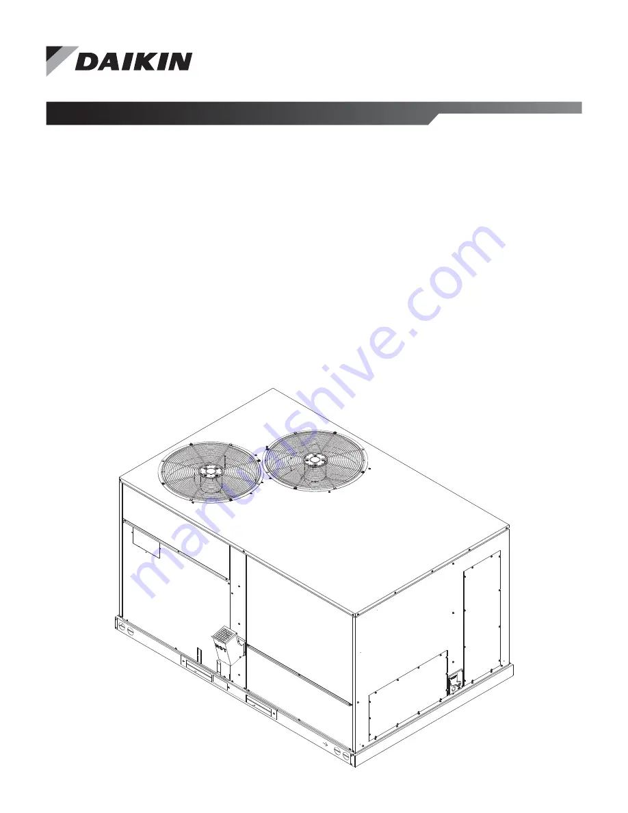
Maverick
®
I Commercial Package
Rooftop Systems
Heating and Cooling
Models MPSA07D – MPSA12D
7 through 12 Tons
R-410A Refrigerant
Page 1: ...tion and Maintenance IM 971 3 Group Controls Part Number IM 971 Date October 2018 Maverick I Commercial Package Rooftop Systems Heating and Cooling Models MPSA07D MPSA12D 7 through 12 Tons R 410A Refr...
Page 2: ...er Motor 54 MCA and MCOP 54 Auxiliary Heater Data 55 Dimensional Data 56 Unit Dimensions 56 Duct Dimensions 57 Curb Dimensions 57 Performance Data 58 Airflow Performance 58 Accessories 66 Non DDC Econ...
Page 3: ...the manufacturer into onto or in conjunction with the air conditioner you should be aware that the use of unauthorized components accessories or devices may adversely affect the operation of the air c...
Page 4: ...noise and vibration away from bedroom windows Location Considerations WARNING This unit may be used to heat the building or structure during construction if the following installation requirements ar...
Page 5: ...bustion air inlet hood properly installed This hood is shipped in a carton in the blower compartment inside the unit and must be attached when the unit is installed See Figure 46 on page 67 To attach...
Page 6: ...installed Rooftop Installation 1 Before locating the unit on the roof make sure that the roof structure is adequate to support the weight involved See Electrical Physical Tables in this manual THIS IS...
Page 7: ...y Tons kW Corner Weights by Percentage A B C D 7 5 12 5 21 1 44 0 26 34 17 23 Figure 6 Shipping Board Removal Figure 7 Roof Curb SPREADER BAR LIFTING BEAM CABLE OR CHAIN CENTER OF GRAVITY CENTER OF GR...
Page 8: ...carbon monoxide poisoning that could result in personal injury or death HGRH System The HGRH system controls both cooling and humidity loads In addition to two stages of cooling the unit includes two...
Page 9: ...75 to close fan proving switch before ramping to the desired speed Since the VFD operates on 24VDC control voltage a blower relay with 24VAC across the coil is used to turn the VFD on Blower speeds a...
Page 10: ...ory specified or approved parts In the commonwealth of Massachusetts installation must be performed by a licensed plumber or gas fitter for appropriate fuel Figure 9 Backup Wrench Location Figure 10 S...
Page 11: ...Natural Gas 5 10 5 3 5 LP Gas 11 13 10 Supply and manifold pressure taps are located on the gas valve body 1 8 N P T and on the manifold Use a properly calibrated manometer gauge for accurate gas pre...
Page 12: ...ng the furnace input make certain that all other gas units are shut OFF with the exception of pilot burners Time the meter with only the furnace in operation IMPORTANT NOTE FOR ALTITUDES ABOVE 2 000 F...
Page 13: ...n the unit rating plate 4 For through the base wiring entry reference Figure 13 All fittings and conduit are field supplied for this application Reference the chart with Table 10 on page 14 for proper...
Page 14: ...rise 35 C when installed in accordance with the manufacturer s instructions Internal Wiring A diagram of the internal wiring of this unit is located on the inside of control access panel and in this m...
Page 15: ...ptable to most residential 24 volt forced air multi stage systems with electric or fossil fuel auxiliary and is the ultimate for comfort convenience and performance See Figure 16 on page 16 for an opt...
Page 16: ...5 ton units a terminal block is not supplied Use a wirenut to extend from the leads provided in the unit to the thermostat W1 W2 and Y2 are optional depending upon the size and selected options of th...
Page 17: ...Wiring Diagrams www DaikinApplied com 17 IM 971 3 MAVERICK I Figure 17 MPS 012D 208 230 460 Volt Constant Volume Gas Heat Electromechanical Controls...
Page 18: ...IM 971 3 MAVERICK I 18 www DaikinApplied com Wiring Diagrams Figure 17 continued MPS 012D 208 230 460 Volt Constant Volume Gas Heat Electromechanical Controls...
Page 19: ...Wiring Diagrams www DaikinApplied com 19 IM 971 3 MAVERICK I Figure 18 MPS 007 010D 208 230 460 Volt Constant Volume Gas Heat DDC Controls...
Page 20: ...IM 971 3 MAVERICK I 20 www DaikinApplied com Wiring Diagrams Figure 18 continued MPS 007 010D 208 230 460 Volt Constant Volume Gas Heat DDC Controls...
Page 21: ...Wiring Diagrams www DaikinApplied com 21 IM 971 3 MAVERICK I Figure 19 MPS 007 010D 208 230 460 Volt Two Speed SAF Gas Heat Electromechanical Controls...
Page 22: ...IM 971 3 MAVERICK I 22 www DaikinApplied com Wiring Diagrams Figure 19 continued MPS 007 010D 208 230 460 Volt Two Speed SAF Gas Heat Electromechanical Controls...
Page 23: ...Wiring Diagrams www DaikinApplied com 23 IM 971 3 MAVERICK I Figure 20 MPS 012D 208 230 460 Volt Two Speed SAF Gas Heat Electromechanical Controls...
Page 24: ...IM 971 3 MAVERICK I 24 www DaikinApplied com Wiring Diagrams Figure 20 continued MPS 012D 208 230 460 Volt Two Speed SAF Gas Heat Electromechanical Controls...
Page 25: ...Wiring Diagrams www DaikinApplied com 25 IM 971 3 MAVERICK I Figure 21 MPS 007 010D 208 230 460 Volt Two Speed SAF Gas Heat DDC Controls...
Page 26: ...IM 971 3 MAVERICK I 26 www DaikinApplied com Wiring Diagrams Figure 21 continued MPS 007 010D 208 230 460 Volt Two Speed SAF Gas Heat DDC Controls...
Page 27: ...Wiring Diagrams www DaikinApplied com 27 IM 971 3 MAVERICK I Figure 22 MPS 012D 208 230 460 Volt Two Speed SAF Gas Heat DDC Controls...
Page 28: ...IM 971 3 MAVERICK I 28 www DaikinApplied com Wiring Diagrams Figure 22 continued MPS 012D 208 230 460 Volt Two Speed SAF Gas Heat DDC Controls...
Page 29: ...Wiring Diagrams www DaikinApplied com 29 IM 971 3 MAVERICK I Figure 23 MPS 007 010D 208 230 460 Volt Constant Volume Electromechanical Controls...
Page 30: ...IM 971 3 MAVERICK I 30 www DaikinApplied com Wiring Diagrams Figure 23 continued MPS 007 010D 208 230 460 Volt Constant Volume Electromechanical Controls...
Page 31: ...Wiring Diagrams www DaikinApplied com 31 IM 971 3 MAVERICK I Figure 24 MPS 012D 208 230 460 Volt Constant Volume Gas Heat DDC Controls...
Page 32: ...IM 971 3 MAVERICK I 32 www DaikinApplied com Wiring Diagrams Figure 24 continued MPS 012D 208 230 460 Volt Constant Volume Gas Heat DDC Controls...
Page 33: ...Wiring Diagrams www DaikinApplied com 33 IM 971 3 MAVERICK I Figure 25 MPS 007 010D 208 230 460 Volt Constant Volume Cooling Only Electromechanical Controls...
Page 34: ...IM 971 3 MAVERICK I 34 www DaikinApplied com Wiring Diagrams Figure 25 continued MPS 007 010D 208 230 460 Volt Constant Volume Cooling Only Electromechanical Controls...
Page 35: ...Wiring Diagrams www DaikinApplied com 35 IM 971 3 MAVERICK I Figure 26 MPS 012D 208 230 460 Volt Constant Volume Cooling Only Electromechanical Controls...
Page 36: ...IM 971 3 MAVERICK I 36 www DaikinApplied com Wiring Diagrams Figure 26 continued MPS 012D 208 230 460 Volt Constant Volume Cooling Only Electromechanical Controls...
Page 37: ...Wiring Diagrams www DaikinApplied com 37 IM 971 3 MAVERICK I Figure 27 MPS 007 010D 208 230 460 Volt Two Speed SAF Cooling Only Electromechanical Controls...
Page 38: ...IM 971 3 MAVERICK I 38 www DaikinApplied com Wiring Diagrams Figure 27 continued MPS 007 010D 208 230 460 Volt Two Speed SAF Cooling Only Electromechanical Controls...
Page 39: ...Wiring Diagrams www DaikinApplied com 39 IM 971 3 MAVERICK I Figure 28 MPS 012D 208 230 460 Volt Two Speed SAF Cooling Only Electromechanical Controls...
Page 40: ...IM 971 3 MAVERICK I 40 www DaikinApplied com Wiring Diagrams Figure 28 continued MPS 012D 208 230 460 Volt Two Speed SAF Cooling Only Electromechanical Controls...
Page 41: ...Wiring Diagrams www DaikinApplied com 41 IM 971 3 MAVERICK I Figure 29 MPS 007 010D 208 230 460 Volt Constant Volume Cooling Only DDC Controls...
Page 42: ...IM 971 3 MAVERICK I 42 www DaikinApplied com Wiring Diagrams Figure 29 continued MPS 007 010D 208 230 460 Volt Constant Volume Cooling Only DDC Controls...
Page 43: ...Wiring Diagrams www DaikinApplied com 43 IM 971 3 MAVERICK I Figure 30 MPS 012D 208 230 460 Volt Constant Volume Cooling Only DDC Controls...
Page 44: ...IM 971 3 MAVERICK I 44 www DaikinApplied com Wiring Diagrams Figure 30 continued MPS 012D 208 230 460 Volt Constant Volume Cooling Only DDC Controls...
Page 45: ...Wiring Diagrams www DaikinApplied com 45 IM 971 3 MAVERICK I Figure 31 MPS 007 010D 208 230 460 Volt Two Speed SAF Cooling Only DDC Controls...
Page 46: ...IM 971 3 MAVERICK I 46 www DaikinApplied com Wiring Diagrams Figure 31 continued MPS 007 010D 208 230 460 Volt Two Speed SAF Cooling Only DDC Controls...
Page 47: ...Wiring Diagrams www DaikinApplied com 47 IM 971 3 MAVERICK I Figure 32 MPS 012D 208 230 460 Volt Two Speed SAF Cooling Only DDC Controls...
Page 48: ...IM 971 3 MAVERICK I 48 www DaikinApplied com Wiring Diagrams Figure 32 continued MPS 012D 208 230 460 Volt Two Speed SAF Cooling Only DDC Controls...
Page 49: ...Wiring Diagrams www DaikinApplied com 49 IM 971 3 MAVERICK I Figure 33 MPS 007 010D 208 230 460 Volt Two Speed SAF with HGRH DDC Controls...
Page 50: ...IM 971 3 MAVERICK I 50 www DaikinApplied com Wiring Diagrams Figure 33 continued MPS 007 010D 208 230 460 Volt Two Speed SAF with HGRH DDC Controls...
Page 51: ...Wiring Diagrams www DaikinApplied com 51 IM 971 3 MAVERICK I Figure 34 MPS 012D 208 230 460 Volt Two Speed SAF with HGRH DDC Controls...
Page 52: ...IM 971 3 MAVERICK I 52 www DaikinApplied com Wiring Diagrams Figure 34 continued MPS 012D 208 230 460 Volt Two Speed SAF with HGRH DDC Controls...
Page 53: ...1 01 10 9 1 01 13 8 1 28 Rows fpi fpcm 1 20 8 1 20 8 1 20 8 2 18 7 Refrigerant control TX valves TX valves TX valves TX valves Drain connection in mm 1 0 75 19 05 1 0 75 19 05 1 0 75 19 05 1 0 75 19...
Page 54: ...50 HP Compressor 1 7 7 5 10 6 Amps RLA Comp 1 9 6 12 5 14 8 12 8 Amps LRA Comp 1 84 100 130 100 HP Compressor 2 N A N A N A 6 Amps RLA Comp 2 N A N A N A 12 8 Amps LRA Comp 2 N A N A N A 100 Condenser...
Page 55: ...P 14 4 17 3 26 30 DD20CP 19 8 23 8 35 35 DD30CP 28 8 34 6 48 50 DD40CP 39 6 47 6 64 70 MPS 008D Medium High Static Drive NONE 22 24 30 35 DD10CP 9 9 11 9 27 30 DD15CP 14 4 17 3 33 35 DD20CP 19 8 23 8...
Page 56: ...NEL BLOWER ACCESS PANEL HEAT EXCHANGER 150 MODEL 60 1524 mm 090 THRU 120 MODELS 50 1270 mm 89 2261 mm 577 8 1470 mm CONTROL ACCESS SERVICE DISCONNECT KNOCKOUT ACCESS PANEL COMPRESSOR FILTER ACCESS PAN...
Page 57: ...89 mm 371 2 953 mm 51 8 130 mm 197 8 505 mm 217 8 555 mm 593 8 1510 mm 57 8 149 mm 51 4 133 mm 15 381 mm 291 2 749 mm 13 330 mm Designates Metric Conversions 901 8 2289 mm 281 2 724 mm 63 4 171 mm 51...
Page 58: ...1095 2340 3300 1557 628 1126 657 1166 685 1210 713 1256 741 1306 768 1359 794 1414 820 1473 846 1535 871 1600 896 1668 920 1739 944 1813 967 1890 989 1970 1012 2053 1033 2139 1055 2229 1075 2321 1096...
Page 59: ...700 1746 663 1332 694 1393 724 1456 754 1521 783 1587 811 1654 838 1723 865 1793 891 1865 916 1938 941 2013 965 2089 988 2167 1010 2246 1032 2326 1053 2408 1073 2491 1092 2576 1111 2662 1129 2750 3800...
Page 60: ...1456 754 1521 783 1587 811 1654 838 1723 865 1793 891 1865 916 1938 941 2013 965 2089 988 2167 1010 2246 1032 2326 1053 2408 1073 2491 1092 2576 1111 2662 1129 2750 3800 1793 678 1400 708 1464 738 15...
Page 61: ...725 1447 753 1504 780 1563 807 1625 833 1690 860 1759 886 1830 911 1905 937 1982 961 2063 986 2146 1010 2233 1034 2322 1057 2415 1081 2510 1103 2609 1126 2711 3800 1793 653 1360 681 1409 709 1460 737...
Page 62: ...090 1130 3192 1147 3296 1164 3402 4300 2029 751 1784 779 1861 806 1939 832 2019 858 2100 883 2184 908 2269 932 2356 955 2445 978 2536 1000 2629 1022 2723 1043 2819 1063 2917 1082 3017 1101 3118 1119 3...
Page 63: ...54 1132 3163 1153 3274 4300 2029 720 1704 746 1769 772 1837 797 1907 823 1981 847 2057 872 2135 896 2217 920 2301 943 2387 966 2477 989 2569 1012 2664 1034 2761 1055 2861 1077 2964 1098 3069 1118 3178...
Page 64: ...54 958 2944 980 3036 1000 3135 1020 3239 1039 3349 1057 3465 1074 3588 1090 3716 1105 3849 1120 3989 1133 4135 1146 4287 1158 4444 1168 4608 1178 4777 1187 4953 1196 5134 1203 5321 1209 5514 1215 5713...
Page 65: ...0 1015 3256 1034 3354 1053 3453 1070 3552 1087 3653 1104 3754 1120 3856 1135 3959 1149 4063 1162 4167 1175 4273 1188 4379 1199 4486 1210 4594 1220 4703 5300 2501 991 3217 1010 3315 1030 3415 1048 3515...
Page 66: ...9 OA damper 6 12 ton Manual MXRF ADA1 26 12 21 10 OA damper Electromechanical Controls 6 12 ton Motorized MXRF ADB1 43 19 38 17 OA damper DDC Controls 6 12 ton Motorized MXRF ADC4 43 19 38 17 Power E...
Page 67: ...damper Single enthalpy CO2 input sensor available Field assembled hood ships with economizer Economizer ships complete for downflow duct application Field installed power exhaust available Prewired fo...
Page 68: ...bled hood ships with economizer Economizer ships complete for horizontal duct application Field installed power exhaust available If connected to a Building Automation System BAS all economizer functi...
Page 69: ...Single enthalpy CO2 input sensor available Field assembled hood ships with economizer Economizer ships complete for downflow duct application Field installed power exhaust available Prewired for smok...
Page 70: ...ilable Field assembled hood ships with economizer Economizer ships complete for horizontal duct application Field installed power exhaust available If connected to a Building Automation System BAS all...
Page 71: ...Exhaust Power exhaust kit for RXRD 01MDDAM3 RXRD 01MDDBM3 RXRD 01MDHAM3 RXRD 01MDHBM3 economizers RXRX CDF01 Figure 50 Vertical Airflow Power Exhaust Economizer MPS 007D 012D POWER EXHAUST BAROMETRIC...
Page 72: ...eed FLA ea LRA ea CFM L s RPM RXRX CDF01C 2 208 230 1 0 47 2200 1038 3000 1 55 1 1 RXRX CDF01D 2 460 3 0 40 1970 930 2750 0 51 1 9 NOTE 1 CFM is at 0 W C external static pressure 373 8 949 3 mm 16 406...
Page 73: ...ized 12 pin and 4 pin electrical connections Pre configured no field adjustments necessary CO2 sensor input available for Demand Control Ventilation DCV All fresh air damper functions can be viewed at...
Page 74: ...ilable for Demand Control Ventilation DCV All fresh air damper functions can be viewed at the RTU C unit controller display If connected to a Building Automation System BAS all fresh air damper functi...
Page 75: ...uick assembly corners for easy installation Insulating panels provided Opening provided in bottom pan to match the Thru the Curb electrical connection opening provided on the unit base pan Sealing gas...
Page 76: ...ol de energizes inducer blower 18 Control de energizes indoor blower 19 Control in the stand by mode with solid red LED Call For Second Stage After First Stage Established Starting from A 11 1 If a ca...
Page 77: ...W signal 5 Flash Over temperature switch open Operating Instructions DANGER Never test for gas leaks with an open flame It can cause an explosion or fire resulting in property damage personal injury o...
Page 78: ...rols are located on the burner shield These devices sense blockage in the heat exchanger or insufficient combustion air This shuts off the main burners if excessive temperatures occur in the burner co...
Page 79: ...lowed by a qualified installer service agency or gas supplier 1 Turn OFF the electrical power to the unit and set the thermostat to the lowest temperature 2 Shut OFF the gas supply to the unit either...
Page 80: ...t use excessive water pressure Excessive water pressure can bend the fins and tubing of the coil and lead to inadequate unit performance Be careful not to splash water excessively into unit 1 The coil...
Page 81: ...Maintenance www DaikinApplied com 81 IM 971 3 MAVERICK I System Charging Charts Figure 55 System Charging Charts 7 5 Ton Two Stage AC...
Page 82: ...IM 971 3 MAVERICK I 82 www DaikinApplied com Maintenance Figure 56 System Charging Charts 8 5 Ton Two Stage AC...
Page 83: ...Maintenance www DaikinApplied com 83 IM 971 3 MAVERICK I Figure 57 System Charging Charts 10 Ton Two Stage AC...
Page 84: ...IM 971 3 MAVERICK I 84 www DaikinApplied com Maintenance Figure 58 System Charging Charts 12 5 Ton AC...
Page 85: ...Maintenance www DaikinApplied com 85 IM 971 3 MAVERICK I Figure 59 System Charging Charts 7 5 Tons Two Stage with Reheat...
Page 86: ...IM 971 3 MAVERICK I 86 www DaikinApplied com Maintenance Figure 60 System Charging Charts 8 5 Tons Two Stage with Reheat...
Page 87: ...Maintenance www DaikinApplied com 87 IM 971 3 MAVERICK I Figure 61 System Charging Charts 10 0 Tons Two Stage with Reheat...
Page 88: ...IM 971 3 MAVERICK I 88 www DaikinApplied com Maintenance Figure 62 System Charging Charts 12 5 Tons Two Stage with Reheat...
Page 89: ...ttached to unit service panel Recover refrigerant evacuate recharge add filter drier At compressor terminals voltage must be within 10 of rating plate volts when unit is operating Compressor short cyc...
Page 90: ...UT CONTROLS CHECK FOR OPEN LIMIT CHECK IGNITION CONTROL CHASSIS GROUND WIRE CHECK WIRING CHECK INLET GAS PRESSURE CHECK 24 VOLTSTO GAS VALVE CHECK FOR GAS FLOWTO AND FROM VALVE CHECK BURNER CARRYOVER...
Page 91: ...ION REMOVE VALVE LEAD AT GAS VALVE IF VALVE CLOSES RECHECKTHETHERMOSTAT AND WIRING IF OK THEN REPLACE VALVE YES NO SYSTEM RUNS UNTIL CALL FOR HEAT ENDS TROUBLESHOOTING ENDS REPEAT PROCEDURE UNTIL TROU...
Page 92: ...IM 971 3 MAVERICK I 92 www DaikinApplied com Warranty Warranty Replacement Parts To find your local Daikin Certified Parts Distributor go to www DaikinApplied com and select Parts Locator...
Page 93: ......
Page 94: ...nt to its standard terms and conditions of sale including Limited Product Warranty Consult your local Daikin Applied Representative for warranty details To find your local Daikin Applied Representativ...