www.DaikinApplied.com 27
IOM 1210-1 • MAGNITUDE
®
MODEL WMC CHILLERS
o
peraTIon
Procedure for Changing a Setpoint
A list of setpoints along with their default value, available
setting range, and password authority can be found in the
tables under each Setpoint Screen, starting on
page 28
.
Follow the steps listed below in order to change a setpoint.
CAUTION
Many setpoints are interactive. Changes may have an adverse
effect on chiller operation. Only trained operators should be
allowed to change chiller setpoints.
1. Press the applicable Setpoint Group. (A complete
explanation of setpoint content of each group follows this
section.)
2. Select the desired setpoint by pressing the numbered
Setpoint Selection button.
3. Press the CHANGE button to change a setpoint value.
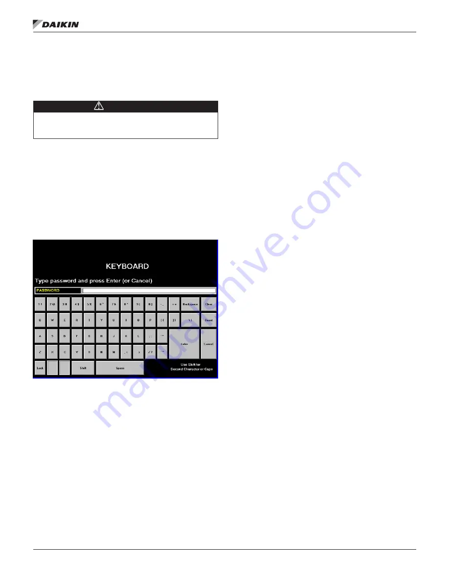
The Keyboard Screen, as shown in
Figure 27
, will
be turned on automatically to facilitate entering the
password.
Figure 27: Keyboard Screen
4. Input the appropriate password number. (Use 100 for
operator level or 2001 for manager level. The technician
level password is only provided to Daikin Applied
technicians) There is a small delay between pressing the
keypad and recording the entry. Be sure that an asterisk
appears in the window before pressing the next number.
5. After inputting the password on the Keyboard Screen,
press ENTER to return to the Setpoint Screen. The
password will remain open for 15 minutes after initiation
and does not need to be re-entered during this period.
6. Press CHANGE again on the Setpoint Screen. The right
side of the screen will become inactive (the background
will turn blue). The Numeric Keypad and Action buttons
in the lower left-hand corner of the screen will become
active (the background will turn green).
7. Setpoints with numeric values can be changed in two
ways:
• Select the desired value by pressing the numbered
buttons on the Numeric Keypad. Press ENTER
to enter the value or CANCEL to cancel the
transaction.
• Press the UP or DOWN button to increase or
decrease the value displayed. Press ENTER
to enter the value or CANCEL to cancel the
transaction.
Some setpoints are text rather than numeric values.
For example, LWT Reset Type on the WATER Setpoint
Screen (
Figure 45 on page 39
) can be “None” or “4-20
ma.” The selection can be made by toggling between
choices using the UP or DOWN button. If dashed lines
appear in the setpoint window it means that toggling in
that direction can go no further, so reverse direction.
Press ENTER to enter the choice or CANCEL to cancel
the transaction.
Once CHANGE is selected, the CANCEL or ENTER
buttons must be pressed before another setpoint can be
selected.
8. Additional setpoints can be changed by selecting another
setpoint on the screen using the Setpoint Selection
buttons or by selecting an entirely new group of setpoints
using the Setpoint Group buttons.
Explanation of Setpoints
There are seven setpoint groups shown on the Setpoint
Screens:
1. TIMERS, sets timers such as start-to-start, etc.
2. ALARMS, sets the limit and shutdown alarms.
3. VALVE, sets the parameters for operation of an optional
field-installed tower bypass valve.
4. TOWER, selects the method of controlling the cooling
tower and sets the parameters for fan staging/VFD.
5. MOTOR, selects motor related setpoints such as amp
limits. Also has maximum and minimum rate of change of
chilled water temperature.
6. MODES, selects various modes of operation such as
control source, multiple compressor staging, pump
staging, BAS protocol, etc.
7. WATER, sets leaving water temperature setpoint, start
and stop delta-T, resets, etc.
Each of the seven setpoint groups are detailed in the following
pages.


