


IM 938-4 / Page 13 of 42
CAUTION
Do not pull on evaporator fan housing, control box or compressor.
Do not lift by pulling on the tubing. Tubing can crack or
bend damaging the unit.
4. If wall sleeve has been previously installed, remove
temporary weather panel.
5. Check all fasteners to make certain they have not come
loose during shipment. Do not loosen bolts holding down
compressor; they are set at the factory.
6. Do not lubricate motors before start-up. Motors are
permanently lubricated.
7. Place Tinnerman clips from bag onto wall sleeve. Clips
and mounting screws are enclosed in a bag attached to
the top of the condenser coil housing.
8. If louver has not been previously installed, connect to
wall sleeve as described above.
9. If louver is supplied by others, as illustrated in
Figure
11
, be sure to install foam type gaskets on all sides of
the condenser coil to prevent recirculation or bypass of
condenser air.
10. Slide chassis into wall sleeve until firmly seated against
weather seals of wall sleeve. Caution: Do not push
on coil surface or control box cover. Make sure the
compressor tubing does not catch when inserting chassis.
11. Secure chassis to wall sleeve with four (4) sheet metal
screws packaged with the Tinnerman clips.
12. Plug electrical cord into receptacle. Excess cord should
be coiled up neatly and stored in the conditioner.
13. Set the manual damper operator in open or closed
position as desired. On units equipped with the optional
electric fresh air damper, set for “AU” or "CL" in the
Configuration Mode. In “AU,” the damper is open
whenever the indoor fan motor is running (AU is Auto
and CL is Closed). Consult
"Maintenance (Scheduled)"
on page 34
for lubrication instructions.
14. Set the indoor fan mode for off cycle on the PC board for
the off cycle selection of 10, 20, 30 minutes or 1 hour off
cycle time. The fan will operate for 2 minutes and shut
down for the selected off cycle period. For continuous
fan operation, the fan mode selection on the touchpad or
remote thermostat must be set to continuous or on. When
the room thermostat is in the cycle or auto mode, it will
cycle the indoor fan when there is a call for heating or
cooling. See wiring diagrams on
page 29, page 30 &
page 31
for jumper placement details.
15. Set the temperature limiting feature to the desired range
of thermostat operations. As shipped, the range is 60°F to
85°F.
16. Replace the air filter and front panel.
17. Connect the low voltage valve wires with theMolex
connection to the valve.
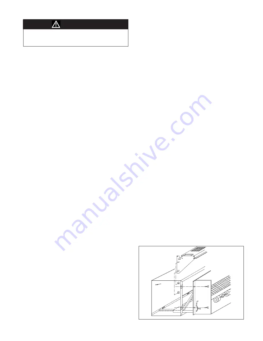
Installing Heat Section
The heat section is designed to be “snapped” into the top
of the wall sleeve (
Figure 15
). There are four square holes
provided in the wall sleeve, two on each side, for coil attach
-
ment. To Assemble the heat section to the wall sleeve:
1. Unpack the heat section and inspect for any shipping
damage. Report any damage found to the carrier.
2. Check the heat section against the plans to make certain the
coil supplied has the connections match the specifcations.
3. Firmly attach the heat section to the wall sleeve by lining
up the heat section hooks with the square holes supplied
in the wall sleeve. Snap the heat section in place by
exerting pressure downward.
4. The valve is always connected to the supply side of
the coil. There are seven possible coil arrangements
available. Each is shown on the next page. Select the
illustration below that matches the coil supplied and pipe
it according to the illustration. Install valve and other
accessories including air vents, steam traps, stop balance
valves, etc., as specified by the design engineer.
5. For valve installed on right side of the unit, make
electrical connection to matching cap extending from
the control box. For left side valve, make electrical
connection to cap mounted to left side of chassis.
Note:
1. When the heating medium is steam, the supply
connection should be attached to the uppermost
tube and the return to the lower tube. The coil is
pitched in the casing to allow drainage of
condensate.
2. When the heating medium is hot water, the supply
connection should be made to the lowermost tube
and the return to the uppermost tube. Hot water
coils should be “flooded” to minimize air
entrapment.
6. The Heat Fan Lockout (HFLO) must be installed on the
return piping of the hot water coil and after the steam
trap for steam heat units. The Factory provides a sensor
snap-on bracket that will fit standard 5/8" OD copper.
Sensor mounting brackets for all other pipe sizes or
materials must be field supplied.
Figure 15: Installing the Cooling Chassis and Hydronic
Heat Section
Factory
Supplied
Holes (2)
Cooling
Chassis
Damper
Actuator
Hydronic Heat Section
Wall Sleeve


